Introduction
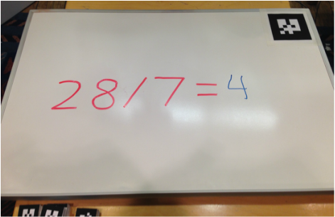
Robots that can draw are cool. Robots that can understand what you draw are cool too. But robots that can understand what you draw, then draw in response to what it understood from your drawing, are super duper cool. For the final project, we made a super duper cool robot.
End Goals
The objective of our EE 125 Final Project was, as specified in our proposal, to program the Baxter robot to “impressively interact” with a human via drawings/writings on a small whiteboard. This entails giving Baxter the ability to:
Why is this project interesting?
While designing the objectives and milestones of our final project, we had a variety of specific robotics related interests in mind - some of which were outside the scope of the class. Through this project, not only did we want to demonstrate a level of mastery with Baxter’s ROS Topic API (as the culmination of all those well spent lab hours), but we also wanted to apply some supplementary knowledge acquired from other courses. Real world robotics is, after all, a wonderful potpourri of mechanical engineering, electrical engineering and computer science. The opportunity to explore the following specific topics was part of what made this project very interesting for us:
Interesting Problems
Throughout the project, we experienced some very interesting problems that we had to solve (and/or work around) to get Baxter to reach end goals. Here are a few:
Real-World Applications
In the construction of the pipeline to get Baxter to meet end goals, we intentionally designed the system to be as flexible as possible. With an extrapolation of our software architecture, combined with stronger hardware and additional hard-coded features, the work from our project can be quite useful to many relevant real-world robotics applications - here’s to name a few:
End Goals
The objective of our EE 125 Final Project was, as specified in our proposal, to program the Baxter robot to “impressively interact” with a human via drawings/writings on a small whiteboard. This entails giving Baxter the ability to:
- Process visual data obtained from onboard camera(s) and isolate important information pertaining to the whiteboard of interest.
- _Perform feats of real-world perception:
a. Transform groups of raw pixel information into manipulable data (character recognition).
b. Location awareness. - Recognize changes in the state of the environment while staying flexible enough to automatically recover from unexpected events/disturbances.
- Formulate appropriate response queues when an environment state meets particular criteria.
- Perform robust path planning for both of its anthropomorphic arms, in an effort to physically draw on the whiteboard.
Why is this project interesting?
While designing the objectives and milestones of our final project, we had a variety of specific robotics related interests in mind - some of which were outside the scope of the class. Through this project, not only did we want to demonstrate a level of mastery with Baxter’s ROS Topic API (as the culmination of all those well spent lab hours), but we also wanted to apply some supplementary knowledge acquired from other courses. Real world robotics is, after all, a wonderful potpourri of mechanical engineering, electrical engineering and computer science. The opportunity to explore the following specific topics was part of what made this project very interesting for us:
- ARTag is a fiducial marker system known chiefly for its applications in augmented reality. We were excited to try it out as part of our whiteboard local awareness module.
- We were enthusiastic to try out some computer vision algorithms with live real-world input, and to challenge ourselves to deal with variations in real-world illumination and noise.
- We were also excited to experiment with robotic arms as advanced as Baxter’s and learn the intricacies of his inverse kinematics library to make him write as neatly as possible.
Interesting Problems
Throughout the project, we experienced some very interesting problems that we had to solve (and/or work around) to get Baxter to reach end goals. Here are a few:
- Baxter’s default inverse kinematics functions do not use linear interpolation, causing his arm to move erratically when told to move from one point to another. When writing on the whiteboard, this caused lines to be curved and would sometimes jam the pen into the whiteboard. This was solved by using linear interpolation between the points where the inverse kinematics was calculated for each point along the line.
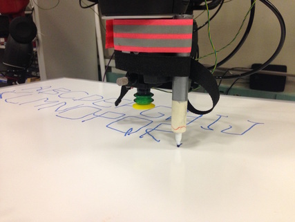
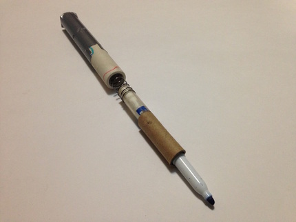
- Due to hardware limitations, the accuracy Baxter’s arms was poor. As a result, we often ran into trouble moving his hands to exactly where we needed them to be to write on the whiteboard. Therefore, we developed a spring loaded marker to maintain contact with the surface while allowing for large variations in z-position.
- Due to the reflectance of the whiteboard and the auto-adjusting features of Baxter’s camera, it was a challenge to get our image pre-processing module (prior to character recognition) to work reliably and dynamically across a wide range of environment illumination.
Real-World Applications
In the construction of the pipeline to get Baxter to meet end goals, we intentionally designed the system to be as flexible as possible. With an extrapolation of our software architecture, combined with stronger hardware and additional hard-coded features, the work from our project can be quite useful to many relevant real-world robotics applications - here’s to name a few:
- Robot assistant: If a disabled/elderly person has difficulty communicating verbally and electronically, he/she can choose to write on a large whiteboard - the robot assistant can then proceed to process the information written on the whiteboard, and automatically respond accordingly (i.e. calling ‘911’ if the person cannot speak nor dial a phone and draws ‘911’). A robot assistant can also serve food to the disabled/elderly, and automatically detect whether or not the person is finished with his/her meal based on the amount of food left on the served tray.
- Factory Robots: Robots are already widely used to perform repetitive mass production tasks. The work from our project can provide the framework for a type of factory robot that can draw/interact with objects dynamically based on their orientation (i.e. write perfectly on packages that are not perfectly aligned with the conveyer belt).
- Robot Art: 2D computer generated art can be very beautiful, but there are still many man-made artistic masterpieces that cannot be completely cloned using only image processing techniques. A good example would be watercoloring. Much of the artistic texture and beauty of watercoloring comes from the physical properties of the brush, paint/water, and light strokes. Using a robot to physically paint watercolor images would be a fantastic alternative to computer generated watercolor art.
Design
Design Criteria
Desired Functionality
Some interesting “impressive interactions” involving writing on a whiteboard include feats
Design Choices
We chose to use ROS (Robot Operating System) because:
Design Tradeoffs
Due to time constraints, we were only able to program Baxter to be able to perform feat 1. Given more time, the problem solving code could have been expanded to more than just basic math problems. Because Baxter only needed to read basic math problems, we were able to restrict the character recognition character set to just numerals, arithmetic operation symbols and the equals sign to improve the accuracy of the results.
Because of issues with calibrating Baxter’s camera, the AR tags were very inaccurate and the calculated location of the whiteboard was not accurate enough to draw on it. Therefore the pose of the whiteboard had to be hard coded.
The first step of image processing depended on hue to identify the marker but the lighting conditions cause the whiteboard to appear blue on the camera. To solve this, we only used red and orange markers.
Final Design
We choose to include all initial design choices for our final design.
- Ability to locate the whiteboard.
a. Pose estimation of the whiteboard to know where to look for the problem and where to write the solution. - Ability to read user input and detect when the user is finished writing.
a. Image processing of the camera image to eliminate noise and unwanted features and generate a clean black and white image of the input handwriting.
b. Robust character recognition of handwritten text and symbols to read a problem from the whiteboard along with the pixel locations of the characters. - Ability to find a solution to the detected problem.
a. Equation solving that can detect that the text is a valid equation and find its corresponding solution. - Ability to write the solution on the whiteboard.
a. Coordinate transformation from camera image to world coordinates to determine where the solution should be drawn.
b. Path planning of the solution text into a series of points in 3D space.
c. Coordinate transformation from the whiteboard frame to the world frame.
d. Inverse kinematics to generate a series of joint angles for the end effector (marker) to move through the solution math to draw the solution.
Desired Functionality
Some interesting “impressive interactions” involving writing on a whiteboard include feats
- User draws a simple math equation on the whiteboard (i.e. “1+1”), Baxter solves the equation by writing the solution on the board (i.e. “=2”).
- User draws one or more smiley faces on the whiteboard, Baxter draws a mustache for each detected smiley face on the board.
- User draws a simple puzzle on the board (i.e. a magic square with empty elements), Baxter solves the puzzle by drawing the solution on the board (i.e. fill in the missing elements for the magic square).
- [Tedious] Pre-program Baxter to visually distinguish edge information between a small list of different objects using machine learning algorithms. User sketches an object (i.e. car), Baxter writes the object label on the whiteboard (i.e. “car”).
- [Tedious] User plays a simple game (i.e. Hangman, connect-4, tic-tac-toe) with Baxter.
Design Choices
We chose to use ROS (Robot Operating System) because:
- We were already familiar with it from our lab assignments.
- It already has many available libraries useful for robotic applications.
- It is already integrated into most robotic systems we could have chosen.
- The hardware was already built, provided for the class and had almost everything we needed.
- Baxter’s arms have a very large reachable space and centimeter accuracy.
- Baxter has cameras on his wrists so they can be easily positioned wherever they are needed.
- Baxter is controlled by ROS and provides coordinate transformation and inverse kinematics libraries.
- It provides a solid white background for vision.
- Whiteboard markers provide thick, colored lines easily distinguishable from the background by hue even when there are bright reflections.
- It provides a large planar surface for Baxter to write on.
- Baxter’s arms are designed to be used in a horizontal workspace such as a table or conveyor belt and therefore has a much greater range of motion horizontally around his waist level than on a vertical plane in front of him.
- Baxter and the user can stand on opposite sides of the whiteboard so they don’t get in each other’s way but Baxter must write upside down so the user can read it.
- Baxter can write the answer upside down just as easily as the other way.
- There is already an open source library that finds the 3D transform of the tags.
Design Tradeoffs
Due to time constraints, we were only able to program Baxter to be able to perform feat 1. Given more time, the problem solving code could have been expanded to more than just basic math problems. Because Baxter only needed to read basic math problems, we were able to restrict the character recognition character set to just numerals, arithmetic operation symbols and the equals sign to improve the accuracy of the results.
Because of issues with calibrating Baxter’s camera, the AR tags were very inaccurate and the calculated location of the whiteboard was not accurate enough to draw on it. Therefore the pose of the whiteboard had to be hard coded.
The first step of image processing depended on hue to identify the marker but the lighting conditions cause the whiteboard to appear blue on the camera. To solve this, we only used red and orange markers.
Final Design
We choose to include all initial design choices for our final design.
Implementation
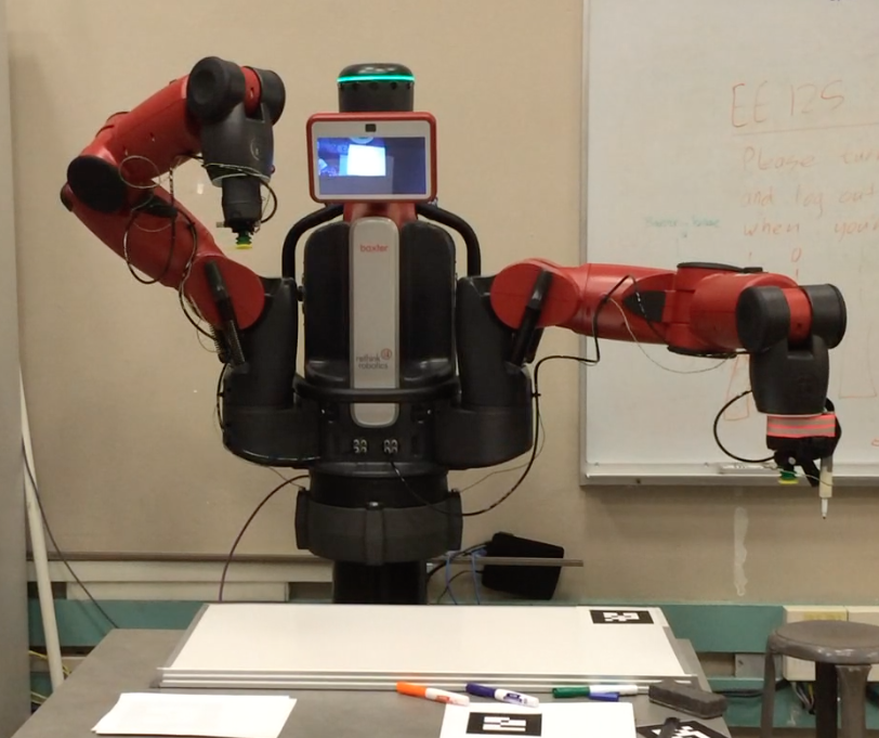
The Hardware:
Baxter
The robotics system we used in this project was Baxter, a robot make by Rethink Robotics. He is controlled through ROS (Robot Operating System) from a Linux desktop computer running our software. He has two 7 degree of freedom arms each with a camera mounted in the wrist.
Baxter
The robotics system we used in this project was Baxter, a robot make by Rethink Robotics. He is controlled through ROS (Robot Operating System) from a Linux desktop computer running our software. He has two 7 degree of freedom arms each with a camera mounted in the wrist.
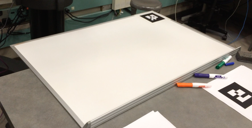
Whiteboard
Just a regular 3 by 2 foot whiteboard placed on a table.
Spring Loaded Marker
Just a regular 3 by 2 foot whiteboard placed on a table.
Spring Loaded Marker
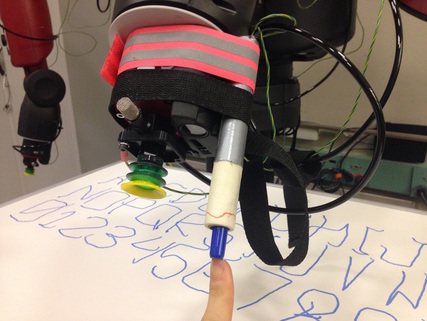
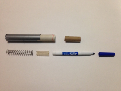
Made from spare parts we had lying around, it consists of a PVC pipe housing with a cap at one end and contains a large compression spring at the top with a whiteboard marker attached to the lower end of the spring. There is a piece of plastic tubing to connect the marker to the spring and there is a cardboard tube around the pen to restrict lateral motion of the marker. The spring allows for about half an inch of error in Baxter’s arm position up or down along the z-axis. This assembly is strapped to Baxter’s left wrist as shown above.
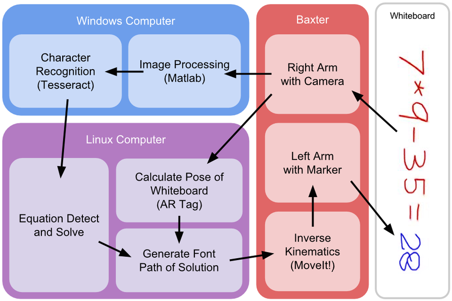 Architecture and Data Flow
Software:
Image Processing
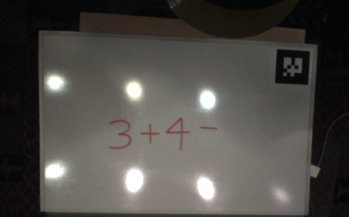
The role of the image processing module is to prepare the raw visual information from Baxter’s right arm camera, perform noise reduction techniques, segment the whiteboard from the background, identify particular areas of interest on the whiteboard, isolate and prepare these areas of interest for character recognition. First, a custom ROS node listens to the camera node and continually captures screenshots. Published BGR8 data from the camera node is converted into an RGB PNG image and saved to disk. This image is then sent through a router via Ethernet cables to a Windows computer that runs MATLAB where the actual image processing portion begins.
Baxter’s arm cameras are quite prone to “fuzzy” artifacts. To normalize this, the screenshot image is passed through a Gaussian filter with an empirically chosen kernel size of 5 and a sigma value of 2.
The filtered image is passed through two pipelines: the first generates a binary mask used to isolate the whiteboard from the background, while the second isolates the text of interest by filtering via the HSV color space.
Pipeline 1
The Gaussian filtered image is first converted to grayscale. 1-dimensional 2-means clustering using uniform initial cluster centroid positions is performed over the raw single channel pixel values. Conceptually, this converts the image dynamically (with a relative rather than parametric threshold) into a binary image where the ‘brighter’ pixels are separated from the ‘darker’ pixels. The binary image is cropped by 20% on all sides and its pixel values are averaged together. If this value is less than the average pixel value of the binary image prior to cropping, then the binary image is inverted. This produces consistent mask labeling for whiteboard vs background, regardless of swapped k-means pixel labeling. We then proceed to filter additional noise from the binary image by removing all 8-connected components with pixel area of less than some small threshold. The resulting binary image is returned as a mask for the whiteboard vs the background.
Pipeline 2
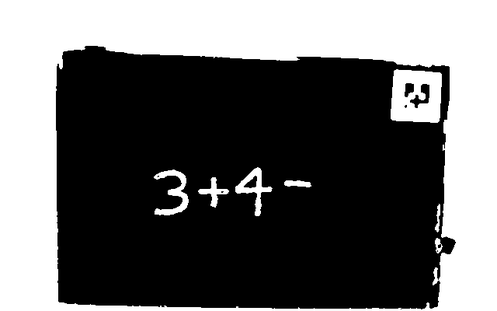
The Gaussian filtered RGB color image is converted into HSV space - the Hue channel is then isolated. All pixel intensity values in this channel are shifted cross the Hue scale by a small value in order to make the color ‘red’ more easily captured (since the default HSL/HSV encodings of RGB has red on both sides of the spectrum). All of the other major rainbow colors should theoretically remain just as easy to capture (aside from maybe purple, depending on the shift value). We then use one of two ways to isolate the text from the whiteboard. For the first method, the mask generated by the first pipeline is applied over the Hue channel, followed by 1-dimensional 2-means clustering using uniform initial cluster centroid positions over the raw pixel values. The centroid labeling the pixels that make up the ‘text area’ on the whiteboard is isolated by comparing the average pixel saturation values in between the 2 clusters. The conceptual idea of this is to isolate ‘color’ (text) from ‘no color’ (whiteboard). Although this method is more flexible, less ad hoc, and more dynamic to varying marker colors, we had much cleaner results using the following observation-based method with a red/orange marker. After applying the binary mask from the first pipeline over the Hue channel, we can perform 1-dimensional 3-means clustering using uniform initial cluster centroid positions over the raw pixel values. Environmental illumination over the whiteboard in both the Cory lab and the Woz is generally more aligned with the darker hues (green/blue/purple), and so the smallest cluster returned from k-means was almost always the red/orange colored text on the whiteboard (we used this method for our live demos). After either text vs. whiteboard isolation method, additional noise is filtered from the binary image by again, removing all 8-connected components with pixel area of less than some small threshold.
The Gaussian filtered RGB color image is converted into HSV space - the Hue channel is then isolated. All pixel intensity values in this channel are shifted cross the Hue scale by a small value in order to make the color ‘red’ more easily captured (since the default HSL/HSV encodings of RGB has red on both sides of the spectrum). All of the other major rainbow colors should theoretically remain just as easy to capture (aside from maybe purple, depending on the shift value). We then use one of two ways to isolate the text from the whiteboard. For the first method, the mask generated by the first pipeline is applied over the Hue channel, followed by 1-dimensional 2-means clustering using uniform initial cluster centroid positions over the raw pixel values. The centroid labeling the pixels that make up the ‘text area’ on the whiteboard is isolated by comparing the average pixel saturation values in between the 2 clusters. The conceptual idea of this is to isolate ‘color’ (text) from ‘no color’ (whiteboard). Although this method is more flexible, less ad hoc, and more dynamic to varying marker colors, we had much cleaner results using the following observation-based method with a red/orange marker. After applying the binary mask from the first pipeline over the Hue channel, we can perform 1-dimensional 3-means clustering using uniform initial cluster centroid positions over the raw pixel values. Environmental illumination over the whiteboard in both the Cory lab and the Woz is generally more aligned with the darker hues (green/blue/purple), and so the smallest cluster returned from k-means was almost always the red/orange colored text on the whiteboard (we used this method for our live demos). After either text vs. whiteboard isolation method, additional noise is filtered from the binary image by again, removing all 8-connected components with pixel area of less than some small threshold.
The sides of the binary image are then trimmed by vertical/horizontal projection. At the end of the image processing module, pipeline 2 returns a relatively clean binary image of the text of interest, captured from the whiteboard.
Character Recognition
The binary image from the image processing module is then passed into Tesseract, an open source optical character recognition engine. We initially tried to implement character recognition by hand, following the project proposal. The original method was as follows. Using vertical projection over the binary image, followed by smoothing convolution and minima detection, we segmented the text in the binary image into individual characters (but very susceptible to noise). Each individual character image is trimmed and a corresponding spatial PHOG (Pyramidal Histogram of Oriented Gradients) feature vector (L2 normalized orientation histograms with 10 bins resolved by modular arithmetic) is constructed. Typically feature vectors at this point should be passed through a Multiclass SVM for identification. Realizing that we had a lack of training data for mathematical symbols such as ‘+’ and ‘=’, we tried various distance metrics over pre-made character templates for identification just to see how far we could get. Overall performance was not reliable, and so we planned to implement the shape recognition algorithm we did in class during the labs. However, due to time constraints, we ultimately decided to find a robust OCR engine to perform the character recognition for us. Tesseract was our best option. After inserting the binary image from the image processing module into Tesseract, we output the recognition results into a text file. We also retrieve information regarding the bounding boxes for the detected characters, and use this information to compute an estimate for the location of where Baxter should begin writing the solution to the math equation. This information is also added to the text file with the recognition results. The finalized text file is sent to the Linux computer for the equation detect and solve module.
The binary image from the image processing module is then passed into Tesseract, an open source optical character recognition engine. We initially tried to implement character recognition by hand, following the project proposal. The original method was as follows. Using vertical projection over the binary image, followed by smoothing convolution and minima detection, we segmented the text in the binary image into individual characters (but very susceptible to noise). Each individual character image is trimmed and a corresponding spatial PHOG (Pyramidal Histogram of Oriented Gradients) feature vector (L2 normalized orientation histograms with 10 bins resolved by modular arithmetic) is constructed. Typically feature vectors at this point should be passed through a Multiclass SVM for identification. Realizing that we had a lack of training data for mathematical symbols such as ‘+’ and ‘=’, we tried various distance metrics over pre-made character templates for identification just to see how far we could get. Overall performance was not reliable, and so we planned to implement the shape recognition algorithm we did in class during the labs. However, due to time constraints, we ultimately decided to find a robust OCR engine to perform the character recognition for us. Tesseract was our best option. After inserting the binary image from the image processing module into Tesseract, we output the recognition results into a text file. We also retrieve information regarding the bounding boxes for the detected characters, and use this information to compute an estimate for the location of where Baxter should begin writing the solution to the math equation. This information is also added to the text file with the recognition results. The finalized text file is sent to the Linux computer for the equation detect and solve module.
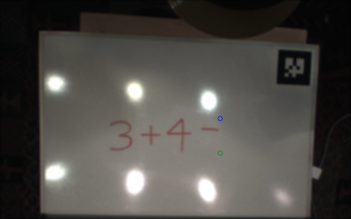
Automatically estimated location on the whiteboard where Baxter should start writing the solution to the math problem. At least two points are necessary to determine font size. Since the whiteboard locations are hard coded into Baxter, these coordinates can be quickly transformed into 3D locations to be passed into the font path generator module.
Pose Calculation of Whiteboard
For finding the pose (position and orientation) of the whiteboard, we attached an ARTag to the top right corner of the whiteboard. We ran the ar_track_alvar ROS node which is a ROS wrapper for the ALVAR library to publish the location in the world frame of any ARTags visible from Baxter’s right hand camera. The node was aware that the camera was at the end of the arm and transformed the location and orientation of the tag from the frame of the camera to the world frame based on the current joint angles and the kinematics stored in Baxter’s URDF file.
The ARTag’s pose is equivalent to the pose of the whiteboard, so once the tag is recognized and located, its transformation matrix is sent to the ROS node that generates the output path of the solution. Because of issues with the accuracy of the ARTags due to incomplete camera calibration, this was not accurate enough to be able to write on the board so the transform of the tag is replaced with a fixed transformation matrix for the whiteboard.
Equation Detect and Solve
This is implemented as a custom ROS node written in Python that simply takes in a string of text from character recognition as the input and sends a string of text as the solution to be drawn on the whiteboard if one exists, otherwise it outputs nothing. To detect if the user is finished writing, it waits for the input to end in an equals sign. If it doesn’t see an equals sign it assumes the user is not finished yet and does nothing. When it sees an equals sign, it then tries to evaluate it using Python’s built in eval() function. If there is an error, it assumes it misread the equation and continues waiting; if it succeeds, it sends its solution to another node to be drawn.
Generate Font Path of Solution
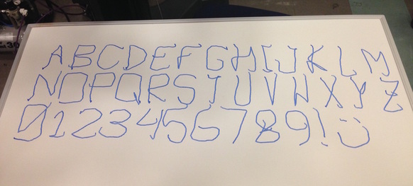
This is also a custom ROS node written in Python. Is has a library of paths that we wrote by hand for the letters A through Z, digits 0 to 9, about 20 symbols, and a smiley face. Each path consists of a list of 2D points that if traced, will draw the character. Unfortunately, we did not have the opportunity to use most of these.
When, the node receives the solution string to draw, it takes each character in the string and chains together the path for each one from the library and generates a list of 3D points. In between each character is a point with non-zero z-position to raise the marker. These points are in the whiteboard coordinate frame and are first translated across the whiteboard to the location directly after where the equals sign was located and then transformed to the world frame using the pose of the whiteboard received earlier. This transformed list of points is then sent to the inverse kinematics library where they are linearly interpolated and converted to a series joint angles for Baxter to follow. This results is Baxter writing the solution.
Inverse Kinematics
This is handled by the MoveIt! library that comes with the Baxter SDK. We use it for calculating the path to move baxter’s arms quickly to different points and also for precise movement while linearly interpolating between points. Inverse kinematics is used to move the right arm with the camera to a point above the whiteboard and also to move the left arm with the marker either out of the way of the camera or, when writing the solution, over the board. It switches to slower, more precise movement when drawing a solution.
Results
Baxter successfully reads math problems from the whiteboard and writes the correct answer after the equals sign. The interactive aspect also works, we can also erase his solution or change the problem on the fly and Baxter will continue finding the solution to the newest problem and writing the answer as long as he sees a math problem. The only issue is that occasionally, he will misread the problem such as seeing a 4 instead of a 9 and write the incorrect answer.
We did not implement any of our stretch goals and we had to simplify a few components of the project such as the pose estimation of the whiteboard and the character recognition to be able to complete the project by the deadline. However, our project meets our initial requirements and works well anyways.
Our video shows one continuous interaction without us touching the computers. You can see Baxter misread the first couple times but afterward read it correctly. Skip to 4:55 to see a successful demonstration.
Conclusion
Discussion
Although we were unable to implement any additional features or stretch goals, our finished solution met our expectations and did well to satisfy the goals that were initially outlined in our project proposal. Our implementation for Baxter also performed surprisingly well during the live demos. He was able to effectively demonstrate the ability to read different math equations on the whiteboard and write the corresponding solutions after the ‘=’ sign with a marker. However, as detailed above, due to a few obstacles we were unable to specifically meet all of the design criteria, including ARTag based pose estimation and custom OCR.
Difficulties
During implementation, we encountered a variety of problems, both big and small. One of the more interesting technical difficulties that we have had to experience (and not mentioned above) was the unavailability of administrative permissions on the Linux computer to use MATLAB and perform some other package installations. Hence, most of the image processing was performed on a Windows computer linked through the router via ethernet cables.
On a more relevant level, we experienced difficulties through nearly every step of development. We experienced noise problems during the image processing module, but ended up formulating an alternative method that was less dynamic, but gave better results for the situation. We had difficulties with our custom implementation of character recognition, so we ended up using an official OCR engine, which gave fantastic results. We ran into accuracy problems using the ARTags for pose estimation, so we hardcoded the position and orientation of the whiteboard into Baxter. We had trouble dealing with Baxter’s default inverse kinematics library, which caused erratic arm movements, so we used linear interpolation to smooth his movements in between points. Overall, we did run into difficulties, but in the end, we still found workarounds in order to achieve our project goals.
Further Improvements
The first notable flaw that our system has involves the second pipeline in the image processing module. To achieve cleaner text images and ultimately better character recognition results, we used an alternative noise filtering and text-isolating approach that took advantage of the hue contrasts between the blue/green/purple environment illumination in the Cory lab/Woz room and the bright red/orange marker drawings. With more time, we would have tried experimenting with smarter and more hue-dynamic text isolating approaches that worked just as well. A second notable flaw that our system has involves the replacement of a fixed transformation matrix for the whiteboard pose estimation module. Given additional time, we would have also tried to experiment with alternative methods to estimate the orientation and position of the whiteboard relative to Baxter’s coordinate system.

