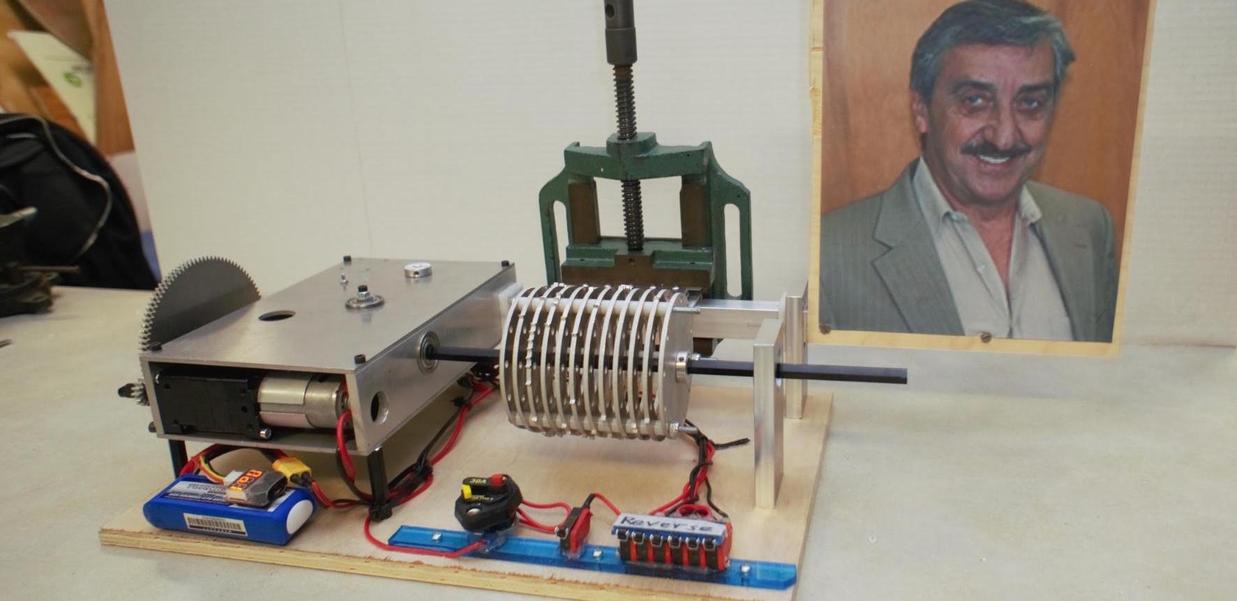
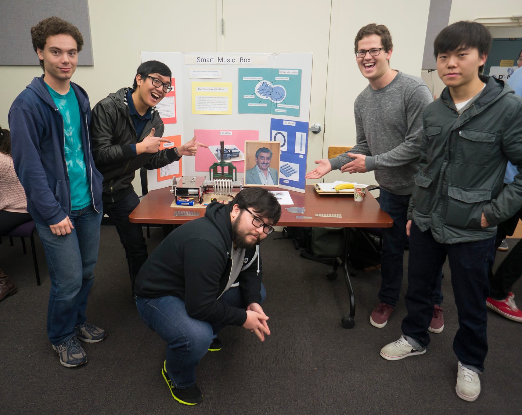
A high-density storage music box that shifts between multiple tracks on the same cylinder. It plays With a Little Help from My Friends by The Beatles and is designed to withstand an EMP, unlike your iPod. Term project for ME 130 – Design of Planar Machinery.
See below for project details.
♯Background
Music is an essential part of the human experience. From the days of creative cavemen, when beating on stretched leather skins made beats, to now, with rock and roll, rap, and rambunctious reggae, music soothes or excites humanity. We wanted to synthesize our love for music with our passion for engineering and create a multiple section music playing device, also known as a “music box.” While this music box may seem primitive compared to the “iPhones” and “Walkmen” of youth today, this device will prove more useful in the coming nuclear holocaust following the depletion of the world’s oil reserves and the ensuing World War III. With this music box, we will maintain morale as humanity rebuilds this device will last as a symbol of ingenuity and innovation long after the tools used to make it has been scorched by radiation.
♯Timeline and Assignments
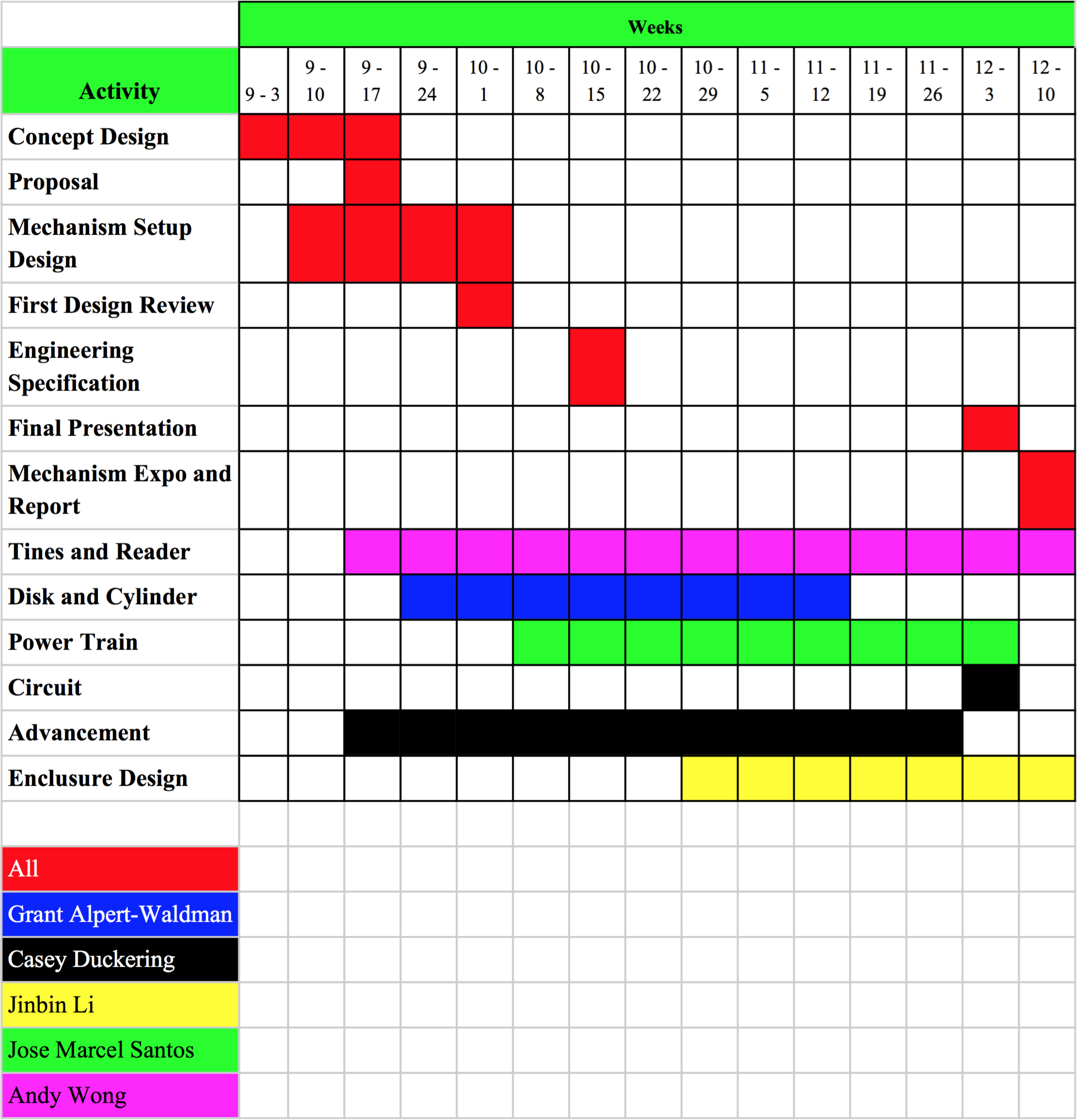
Refer to Appendix A for the Gantt chart.
Responsibilities were as follows: Grant worked on the cylinder, Casey and Jose created the advancement mechanism and powertrain, Casey build the electronics, Andy developed the tines, and Jinbin worked on the enclosure design.
♯Introduction
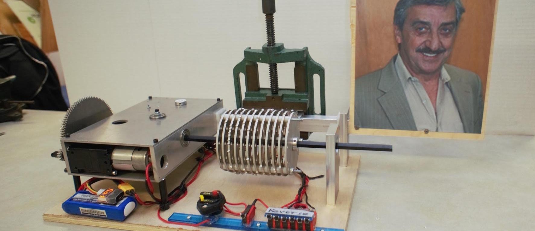
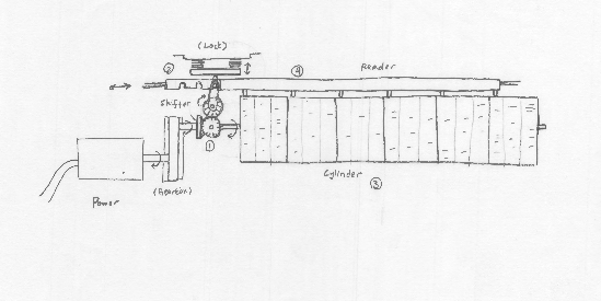
The overall function of this music box is the same as that of a typical music box: musical notes are played by ridges smacking against noteproducing metal tines.
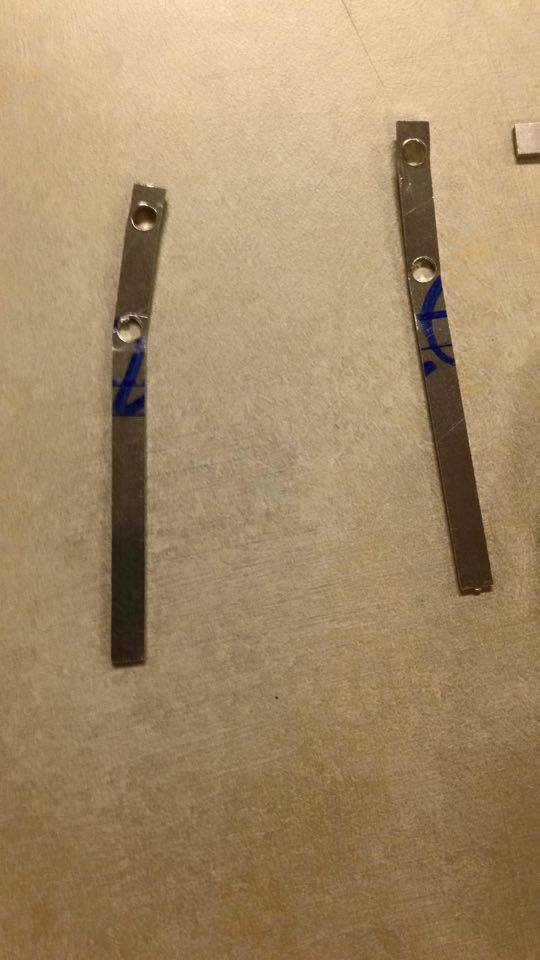
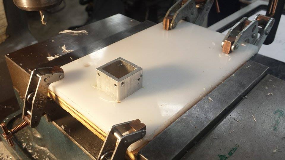
The reader consists of 5 tines and 2 clamping plates. Each of the tines are made with 1/16th inch aluminum. Each tine plays, respectively, do-re-mi-fa-so when plucked the current iteration is in the key of E♭ major. The reader is mounted on the advancement mechanism. The tine lengths were determined after multiple rounds of testing, as detailed in a later section.
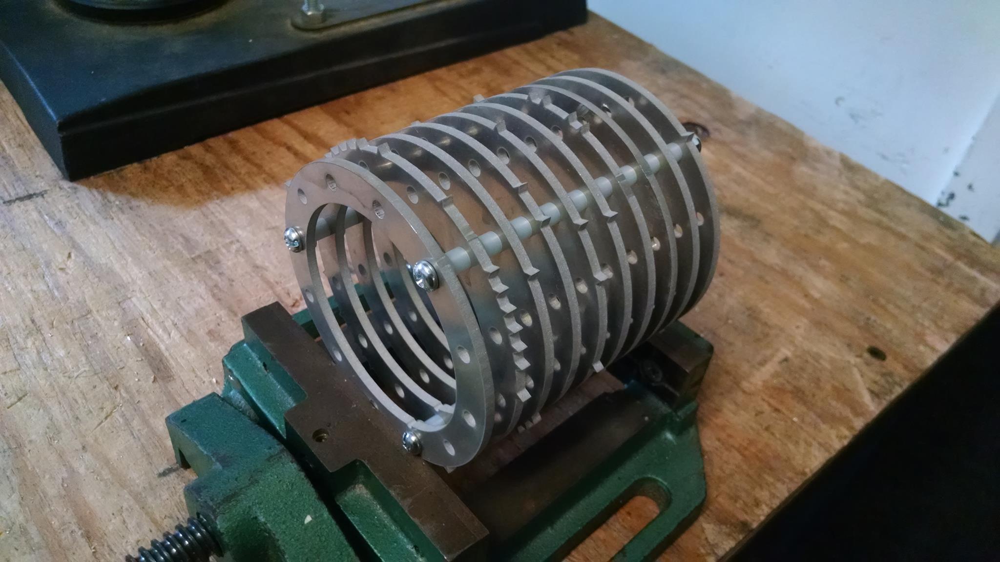
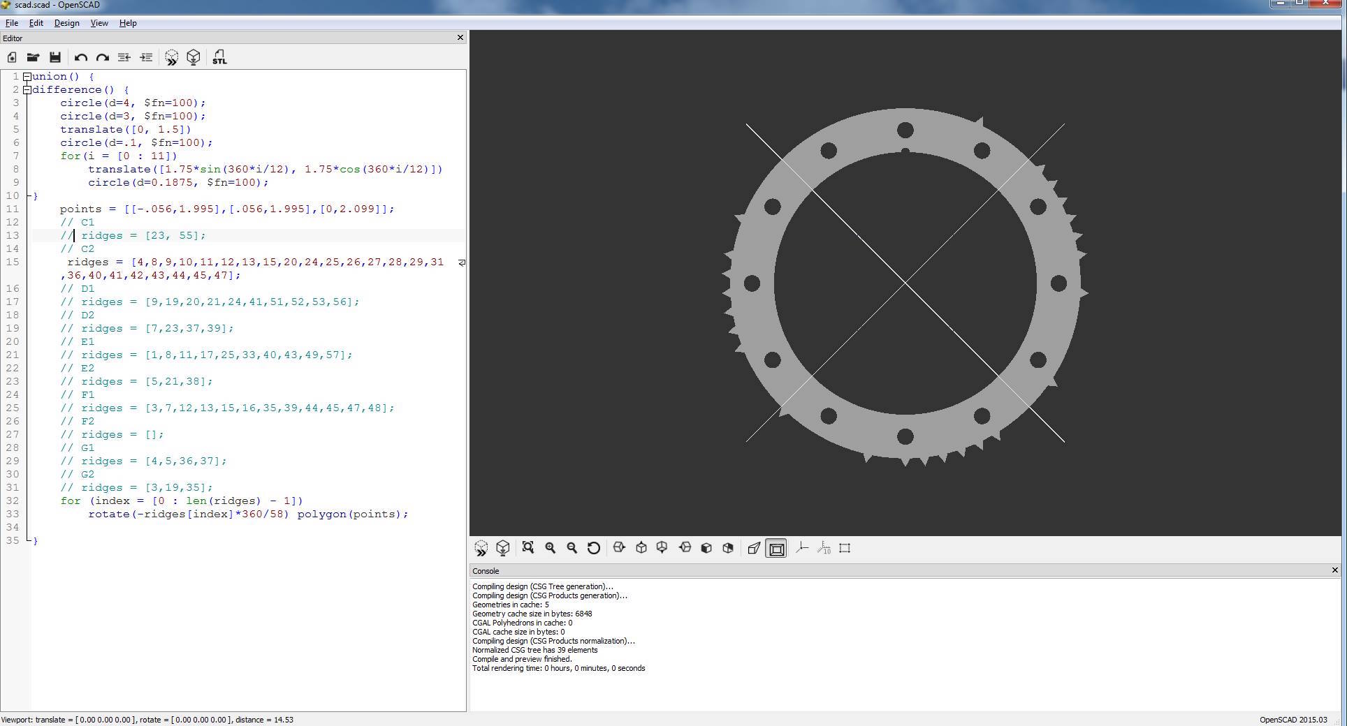
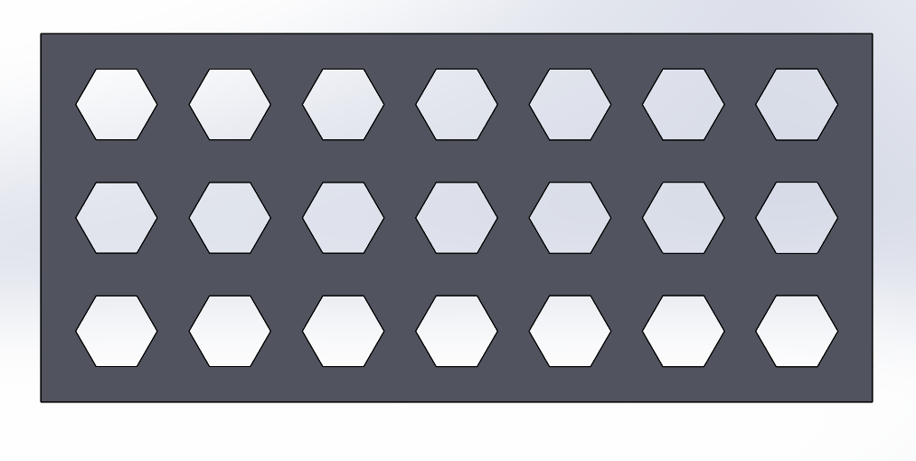
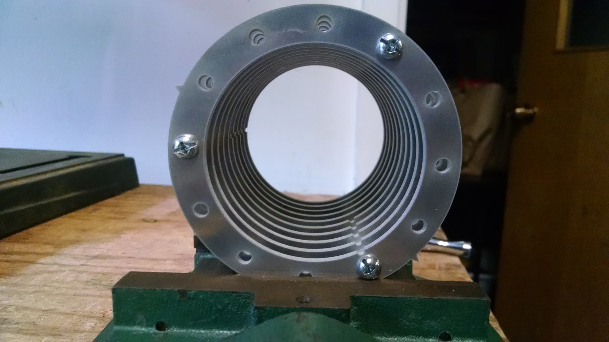
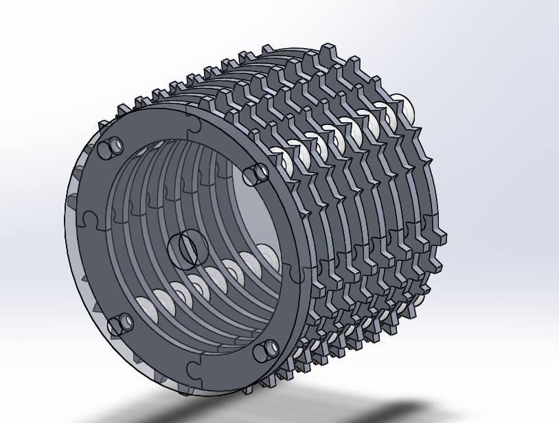
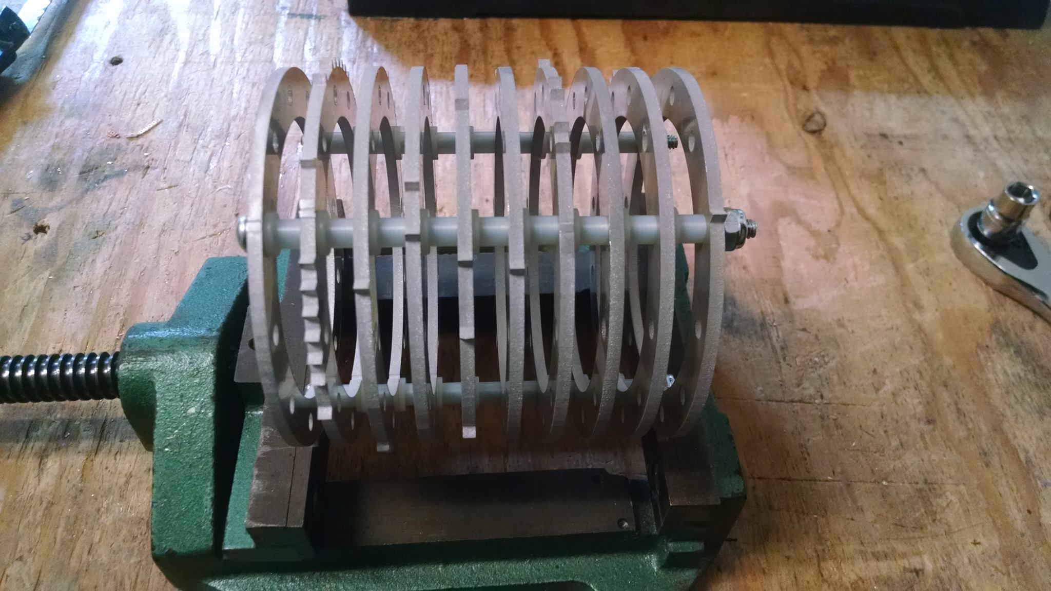
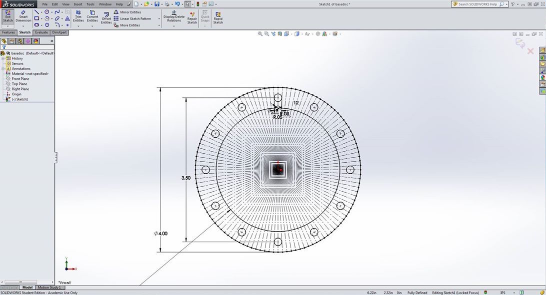
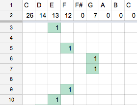
There are 10 discs, made for the 2 sections of the 5 notes. There are a total of 58 possible ridge locations per disc, and there are a total of 72 ridges among all 10 discs. The discs of the cylinder are all water jet from 1⁄8″ aluminum with no extra finish machining required. The song “With A Little Help From My Friends” was transcribed from the sheet music to 8th notes in order to assist with determining the locations of the ridges on each disc, as shown below.
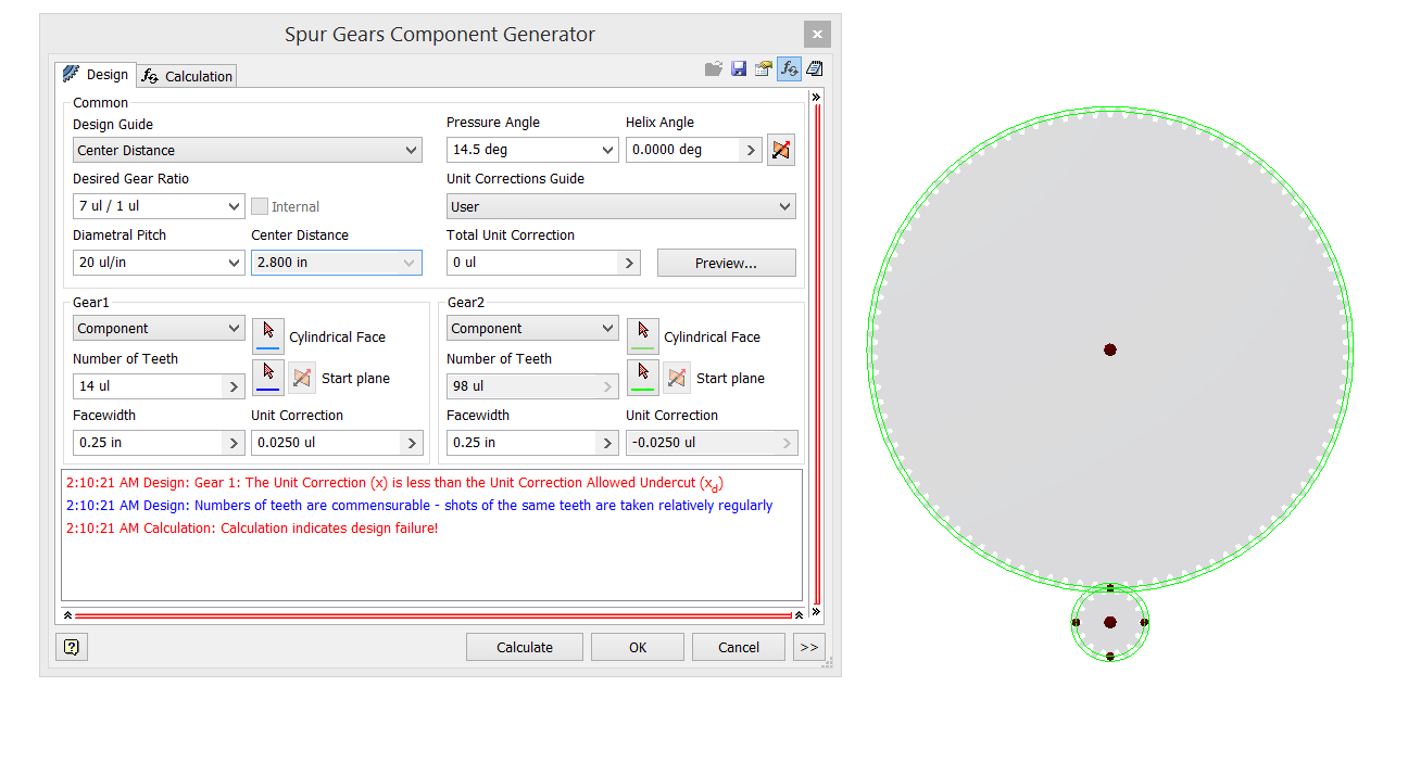
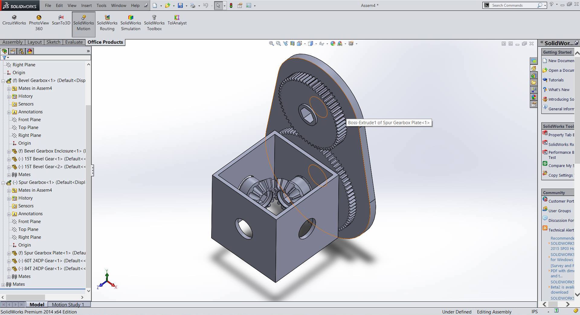
Using OpenSCAD, a programmatic CAD language, the discs were easy once the locations of the ridges were determined. A program creating the disc profiles exported a .DXF directly so that it could be water jet. Each disc was then created, along with end caps with hex holes. The cylinder hex shaft is then geared using spur gears with a teeth ratio of 98:14, or 7:1, so that the cylinder spins at 3 to 4 RPM, necessary for the beat of the song.
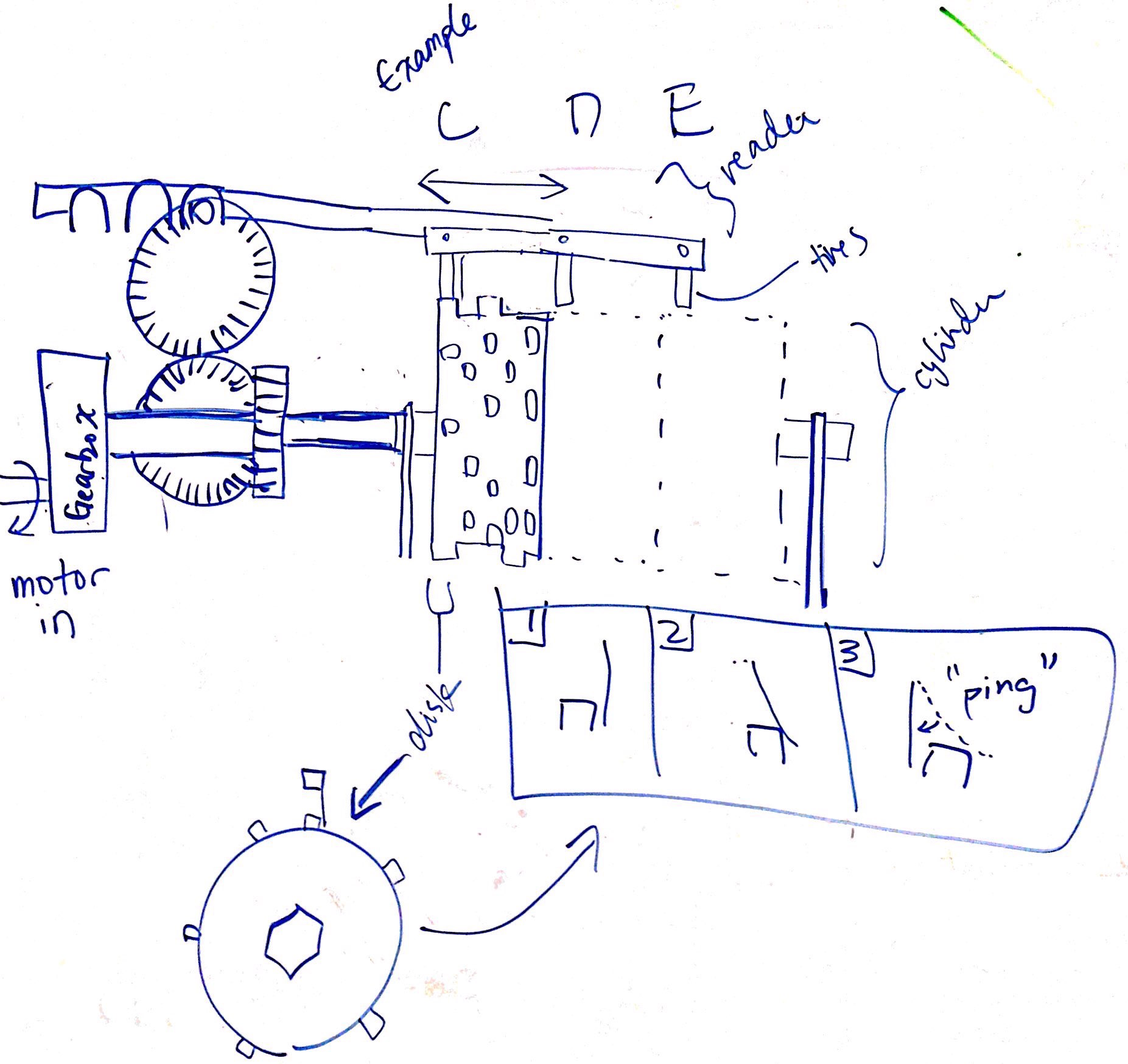
The gear train consists of the motor (a 300:1 planetary gearbox) followed by a 7:1 reduction from the motor to the cylinder shaft. Also connected to the cylinder shaft is a 1:1 bevel gear translating the motion perpendicularly to another shaft. This shaft has a 1:6 spur gear ratio that increases speed for the Geneva advancement mechanism.
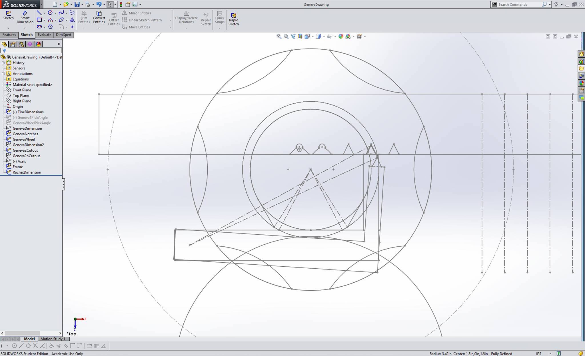
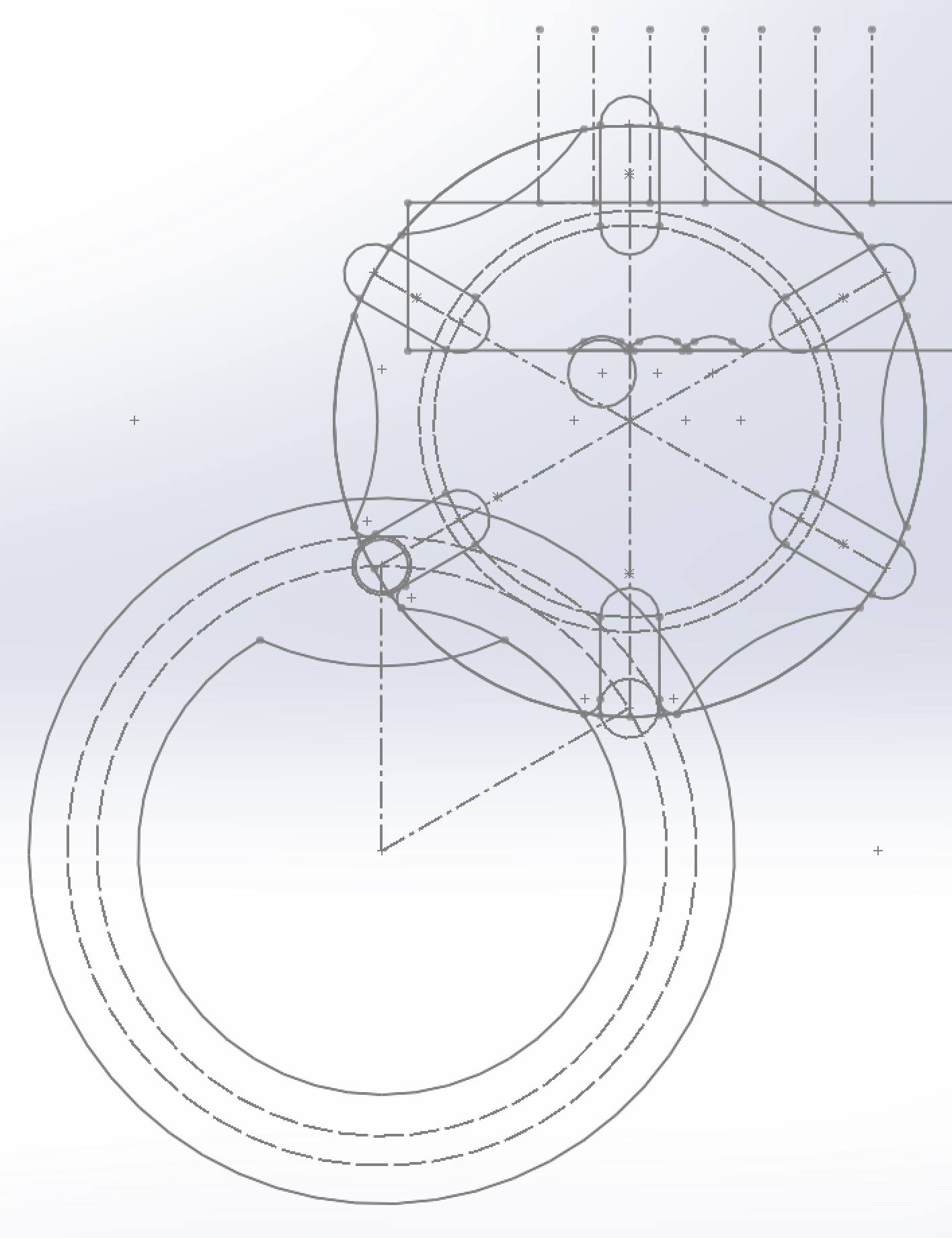
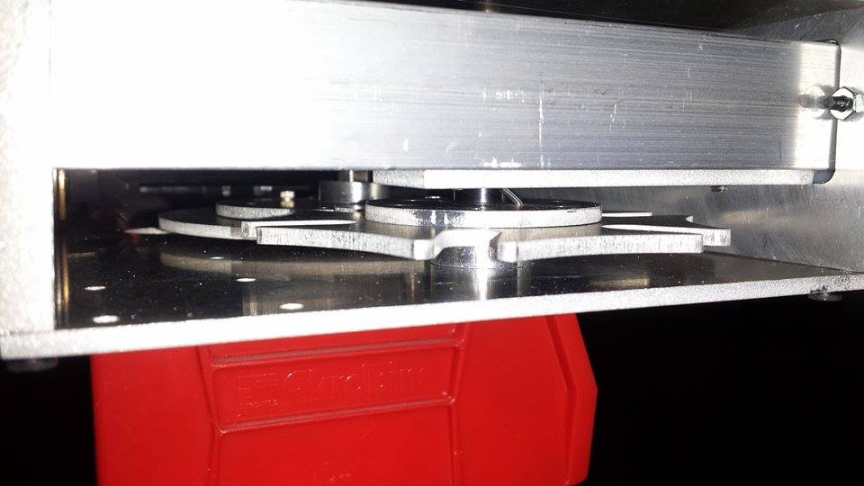
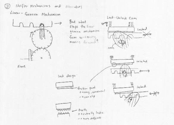
The advancement is powered an increase in speed of 6:1 from the cylinder. This rotates the rotational geneva six times for every one rotation of the cylinder, so that the linear output of the Geneva is performed at the correct speed, which moves at 1/36th of the time per revolution of the disc. This linear Geneva performs the advancement of the reader in 3⁄8″ increments to align the reader with the next set of discs. The linear Geneva also has a ratchet to prevent motion when not desired, which is released by a cam in sync with the linear motion, returning via a tension spring.
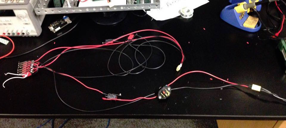
In order to make the system resistant to electromagnetic pulses and radiation, the circuit consists of only 16 Amp limit switches. There is no microcontroller so as to be robust. A forward and a reverse limit switch shut off the motor once the end of the music has been reached, breaking the circuit when triggered. There is also a reverse control switch consisting of six, mechanically toggled together limit switch because we did not have an on hand a highcurrent, dual, doublethrow switch, so this is the improvised method. This reverse is wired to reverse polarity of the motor when triggered without shorting the battery duing the transition. There is also a disconnect switch that performs the same function as the circuit breaker, completely opening the circuit when pressed. The whole circuit runs on a 12 V battery, Lithium Polymer in our case, but able to use a car battery for typical use cases.
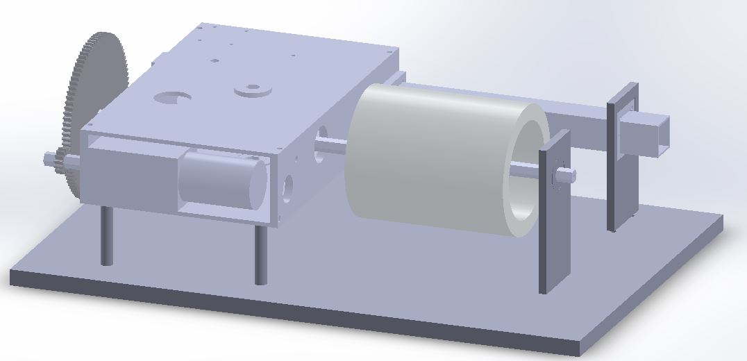
Thus, the device functions by having the cylinder force the readers tines to vibrate and play a note by smacking – once the cylinder revolves a full revolution, the advancement mechanism shifts the reader forward, so that a new round of music can be played.
Power requirements of the system are calculated from the assumption that maximum power would be when all 5 tines are being plucked and the Geneva is advancing the reader (which never happens). Assuming about .57 N-m of torque required per tine, plus some extra for the advancing, we calculated a maximum power requirement of 1.3 W, with 70% efficiency. The power is provided by a 12 V, 3 cell LiPo battery mounted to the base, but can be done with any form of 12 V power.
♯Functional Specifications
- Music Box will play “With A Little Help From My Friends” by The Beatles.
- A single, self-driven power source will spin the data cylinder and advance the reader mechanism.
- Bumps on the data cylinder hit notes on the reader to produce notes.
- For ease of manufacturing, data cylinder will be waterjet discs.
- The device should be of comparable size and weight to other household entertainment devices, such as game console or record players.
♯Engineering Specifications
- Reader note material: ~1/32-1/16″ thick x 1/2-5/8″ wide x 2-3″ long steel strips
- Weight: 5-10 lbs
- Size: Maximum 18″ x 18″ x 18″
- Song tempo: 113 beats per minute
- Data cylinder discs: 1⁄8″ thick x 4″ diameter aluminum disks, spaced 1/4-3/8″ apart. 10 disks total (5 notes, 2 discs each), 40 beats per disk
- Data cylinder size: 4″ diameter x 5.5-6″ long
- Data cylinder speed: 3 RPM
- Reader speed: 1.2 in/s
- Reader Gear Ratio for 3⁄8″-8 TPI lead screw: ~1:200-1:300
- Reader Gear Ratio for rack and pinion or linear geneva: ~1:2-1:5
- Reader Deflection: ~1⁄8″ deflection
- Motor: ~2.44 N-m to play all notes, ~2 Watts max power. Assuming mechanisms 70% efficient and rating for ~1⁄2 max mechanical power.
- Power source: 12-24V DC Power Supply, LiPo Battery, or car battery
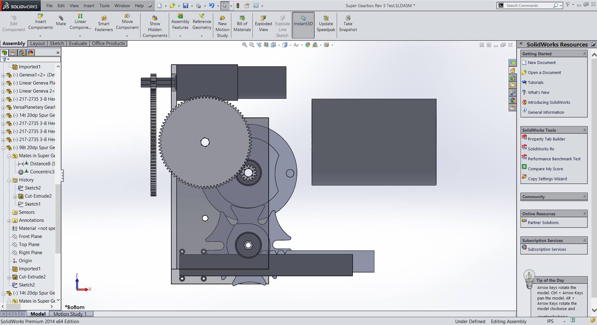
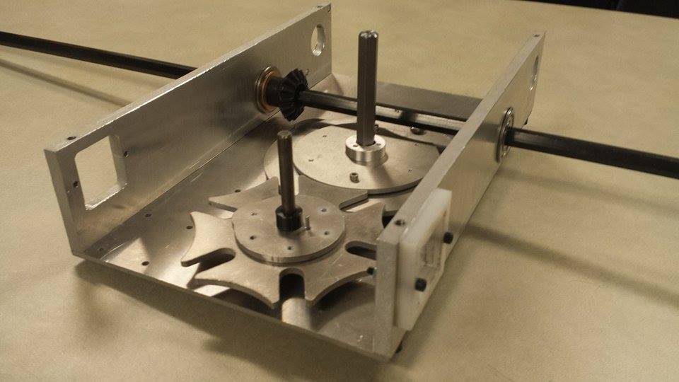
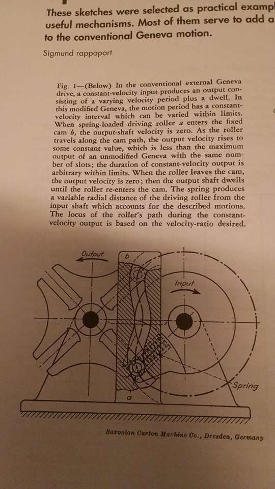
♯Detailed Design: Geneva Mechanism
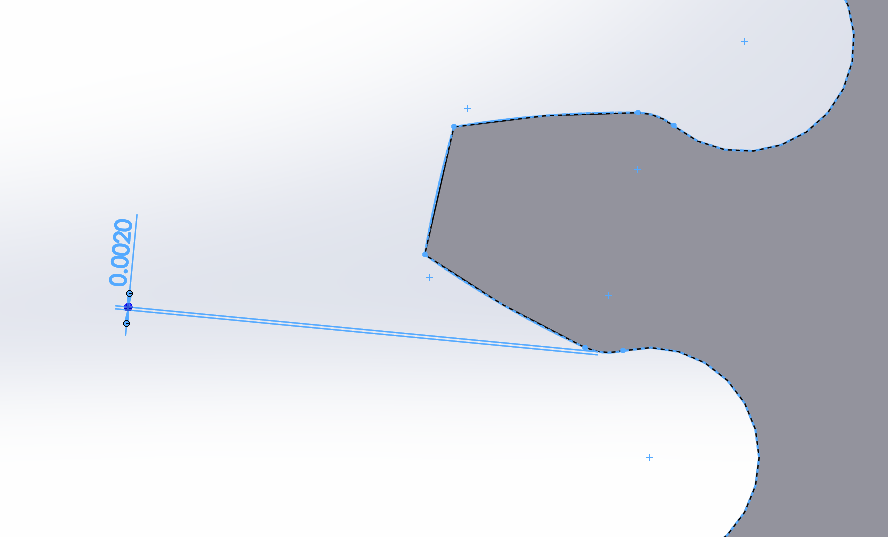
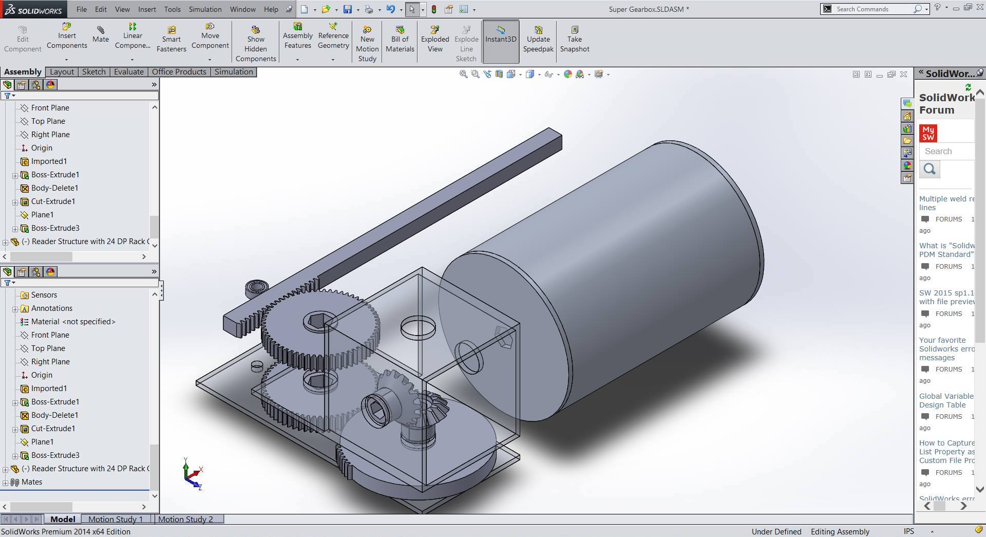
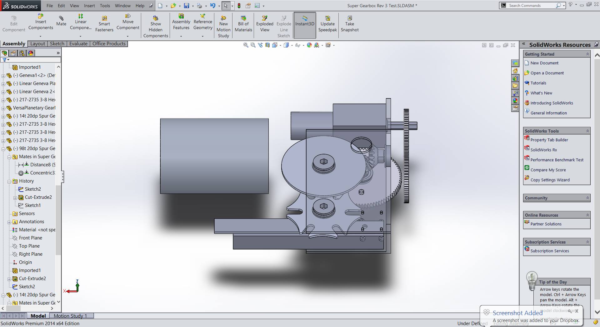
The Geneva was designed in order to translate rotational motion from the powertrain into linear motion for the reader. The sizes were chosen based on similarities to the music discs and further dimensioning was done based on necessary motion. As seen below, the design was parametrized using SolidWorks in order to perform rapid iterations. Normal Geneva mechanisms have tangent pin entry into the slot, but in order to make the mechanism take longer for a revolution, the angle of pin entry to allow for more compact reduction. Using normal tangent methods, there would be a maximum “gear ratio” of 4:1. In order to determine how far the output would travel, SolidWorks was used graphically, drawing different positions and constraining the desired output of 3⁄8″ of linear travel. This design was iterated in order to achieve the perfect output.
♯Detailed Design: Power Train
The power train design was driven by 2 major constraints: angular speed and torque. Since the song is played at 113 beats per minute (or 226 notes per minute if the shortest note played is an eighth note) and since there are 58 notes per disk, the cylinder needed to spin at ~4 RPM.
The torque required is primarily a function of the force needed to deform the reader tines. Since each tine is essentially a cantilevered beam, the force of deflection can be found using the following formula:
$latex F=\frac{3\delta E I}{L^3}&s=3$
Where δ is the deflection, I is the area moment of inertia, and L is the beam length
The formula for a rectangular beam’s area moment of inertia is as follows:
$latex I=\frac{wt^3}{12}&s=3$
Where w is width and t is thickness of the beam
A spreadsheet was made to calculate the necessary force for different materials, tine dimensions, and numbers of notes. Since our final tines were 1/16″ x 1⁄4″ x ~2″ (the final length varies slightly based on the note) 2024 Aluminum and the cylinder has 2″ radius, and the reader has 5 notes, the maximum torque needed is 2.85 N-m or ~403.87 oz-in.
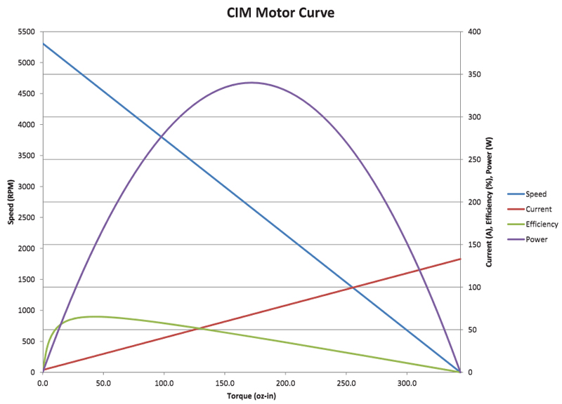
To choose the proper motor and reduction, we need to know stall torque, free (angular) speed, stall current, and free current at the rated voltage. From this information, we can construct a “motor curve,” since speed decreases linearly as torque loading increases and current draw increases linearly with torque. Consequently, mechanical power is a parabolic function of torque and efficiency is a skewed curve which maximizes at ~1⁄4 of stall torque. In other words:
$latex \omega=\frac{\omega_{free}}{\tau_{stall}}\cdot\tau+\omega_{free}&s=3$
Where ω is angular velocity and τ is tourque
$latex \text{Mechanical power}=\omega\cdot\tau&s=3$
$latex \text{Electrical power}=V\cdot I&s=3$
Where V is voltage and I is current
$latex \text{Efficiency}=\frac{\text{Mechanical power}}{\text{Electrical power}}&s=3$
Motor performance can be visualized with a “motor curve” such as the following:
If the torque loading is known, we can control where on the curve the motor performs using gear reductions. The desired ratios can be calculated using the following equation:
$latex \text{Ratio}=\text{Mechanical advantage}=\frac{n_{out}}{n_{in}}=\frac{\tau_{out}}{\tau_{in}}=\frac{\omega_{in}}{\omega_{out}}&s=3$
Where n is the number of teeth on the gears
For maximum efficiency, we set output torque equal to loading and input torque equal to 1⁄4 of stall torque. However, as long as input torque is less than 1⁄2 of stall torque the motor is unlikely to burn out.
To increase cost-efficiency for our prototype, we used a BaneBots RS-555 Brushed DC Motor with a VEXPro 300:1 VersaPlanetary gearbox operating at 12V. At this voltage and reduction, the motor has a stall torque of ~6342.3 oz-in and free speed of ~26 RPM. Although this torque was more than sufficient, the free speed needed a ~7:1 reduction to play spin the cylinder at the right speed. Additionally, the geneva mechanism needed an input speed which was 6x faster than the cylinder.
For maximum musical enjoyment, the reader should not significantly slow down when notes are played. Using the equations above in our spreadsheet, we found that our motor of choice does not slow down appreciably during loading:
| Torque (oz-in) | Speed (RPM) | |
| 0 | 3.69047619 | No Load |
| 60900 | 0 | Stall Torque |
| 403.8747278 | 3.666001805 | All Notes |
| 80.77494556 | 3.685581313 | Single Note |
Both the 7:1 and 1:6 reductions were achieved using custom designed waterjet gears. In particular, the cylinder is attached to a 98t (spur) gear driven by a 14t gear attached to the motor. The first geneva is attached to a 14t gear driven by an 84t gear, which attached to the cylinder’s power train via 15t bevel gears from VEXPro.
We decided to waterjet the spur gears to both learn about gear design as well as to save money. The gears were designed with a 20 DP, 14.5 degree pressure angle profile for compatibility with off-the-shelf gears from VEXPro and AndyMark in case our custom gears did not work. As such, all the gears are driven by 3⁄8″ hex axle. The gear profiles generated in Autodesk Inventor, and modified in SolidWorks.
(See discussion below)
♯Detailed Design: Tines and Reader
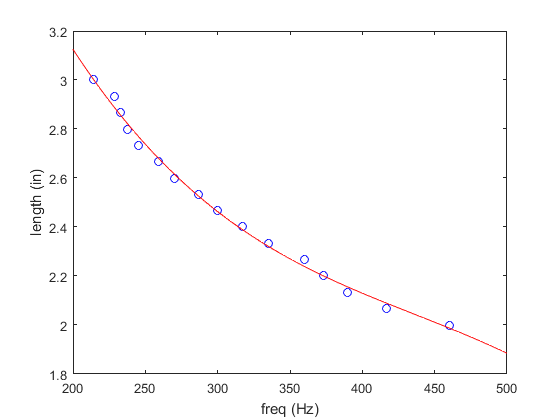
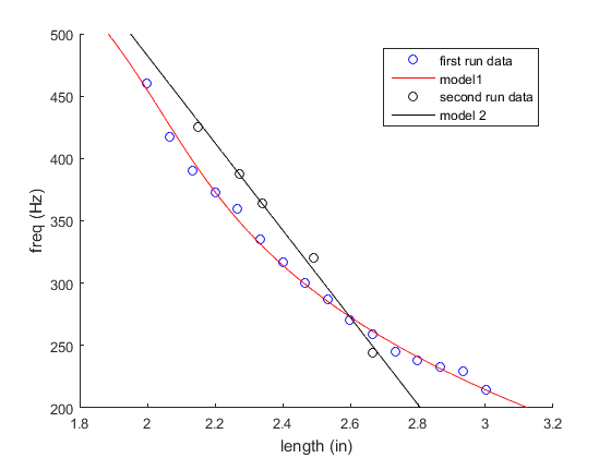
In order to create musical notes with metal tines, we had to generate an experimental model relating tine lengths to frequency there is no data on 1/16th inch aluminum musical vibrations. Thus, after researching a little, we sent in a linearly-increasing-length set of tines to be water-jetted, and measured the resultant frequency of each tine using a tuner. Then we fit a 3rd degree polynomial to that curve.
After doing so, we created a set of tines to play do-re-mi-fa-so in the key of C major – the notes C, D, E, F, G. After sending these in to be water-jetted, we again measured the frequencies of these tines. They did not play anything resembling do-re-mi-fa-so.
In fact, this second model seemed to follow a completely different model. After printing a new set of tines following this model, this time in D major (because the requirements for making tines in C major made the tines sound unmusical), we found that attempts at models predicting the length of the tines were fruitless. After that point, we simply filed down tines to length in order to produce the correct notes. The current set of tines is in E♭ major, as the method of tuning we are using only allows for increases in tine length. Before fabrication, it played at more or less a major scale, do-re-mi-fa-so.
♯Discussion
Several shortcomings came to light as the assembly continued and final designs were created. One of these shortcomings was the inability to precisely align the tines of the reader with the ridges of the cylinder. On the cylinder, we opted for ridges of .15″ to reduce wear and decrease footprint. This led to a very small tolerance for the length of the tines, and because they required finishing in terms of tuning by filing the length, this caused problems in assembly. In order to have the tines make contact with the cylinder, we had to file down the correctly tuned tines to incorrect tunings – otherwise, they would not make a sound. In the future, more precise tuning of the tines or larger ridges to compensate for possible problems, or even a sliding slot to mount the reader onto the square tube would help with these problems.
Several modifications were made to the gear designs to achieve functionality. Due to the gear profile chosen, the 14t gears needed an undercut for proper meshing with the rest of the gears. To compensate for waterjet taper and minimize wear in needed, a .002″ clearance was added to the center-to-center distances between gears, and the 14t gear profile was offset by .003″.
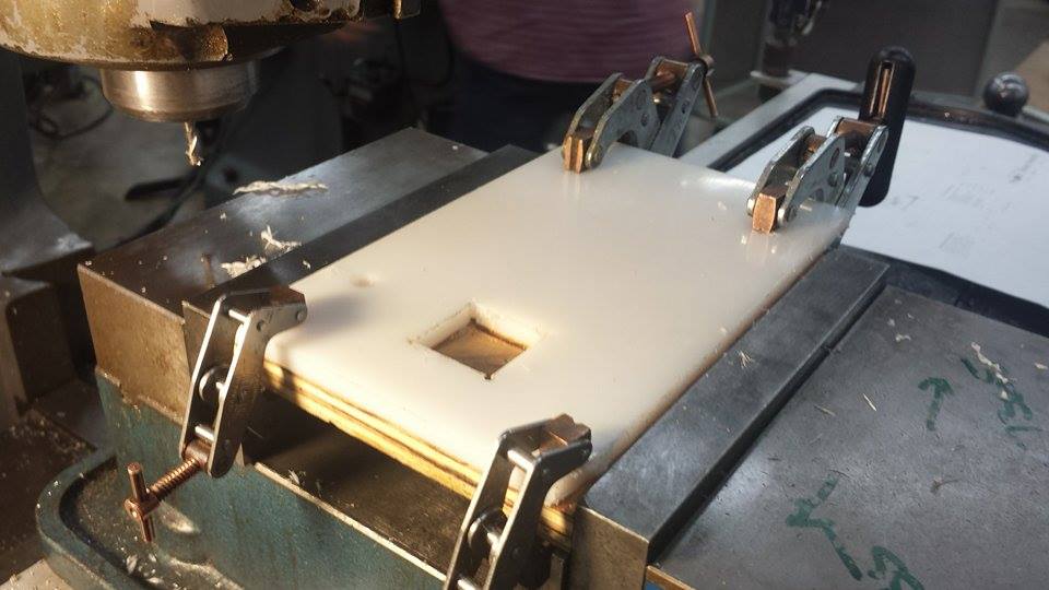
Because we designed for compatibility with VEXPro and AndyMark components, all driven mechanisms use 3⁄8″ (nominal) hex axle. Since the Berkeley Machine Shop did not have a 3⁄8″ hex broach, the bores were all cut out with the waterjet. To achieve a smooth, sliding fit our bores had to be larger than the VEXPro shaft, which is actually undersized at .374″. However, too large of a clearance would introduce unwanted backlash. Additionally, the waterjet taper causes the bore size to be inconsistent between sheet faces. To find the ideal hex bore size, calibration plates were designed and cut with multiple hex bores, offset by .0005″, with 3 bores per size. In the end we found that specifying a .3765″ hex bore in SolidWorks gave us the idea fit.
The weakest point, structurally, in the advancement mechanism is the small pin attached to the second Geneva mechanism. In order to fit within the designed linear mechanism, the pin needed to be very small, on the order of .08″ in diameter. Because this pin drove the whole advancement, the forces were some of the largest, and we broke one pin due to going past the end, snapping under the applied force.
Because of how complicated the Geneva mechanism is, one of the initial mechanism designs involving a rack and pinion would have been more ideal. Instead of having a complicated Geneva, we could use a rack and pinion with only a few teeth on the pinion that would advance the mechanism.
♭Appendix A: Gantt Chart
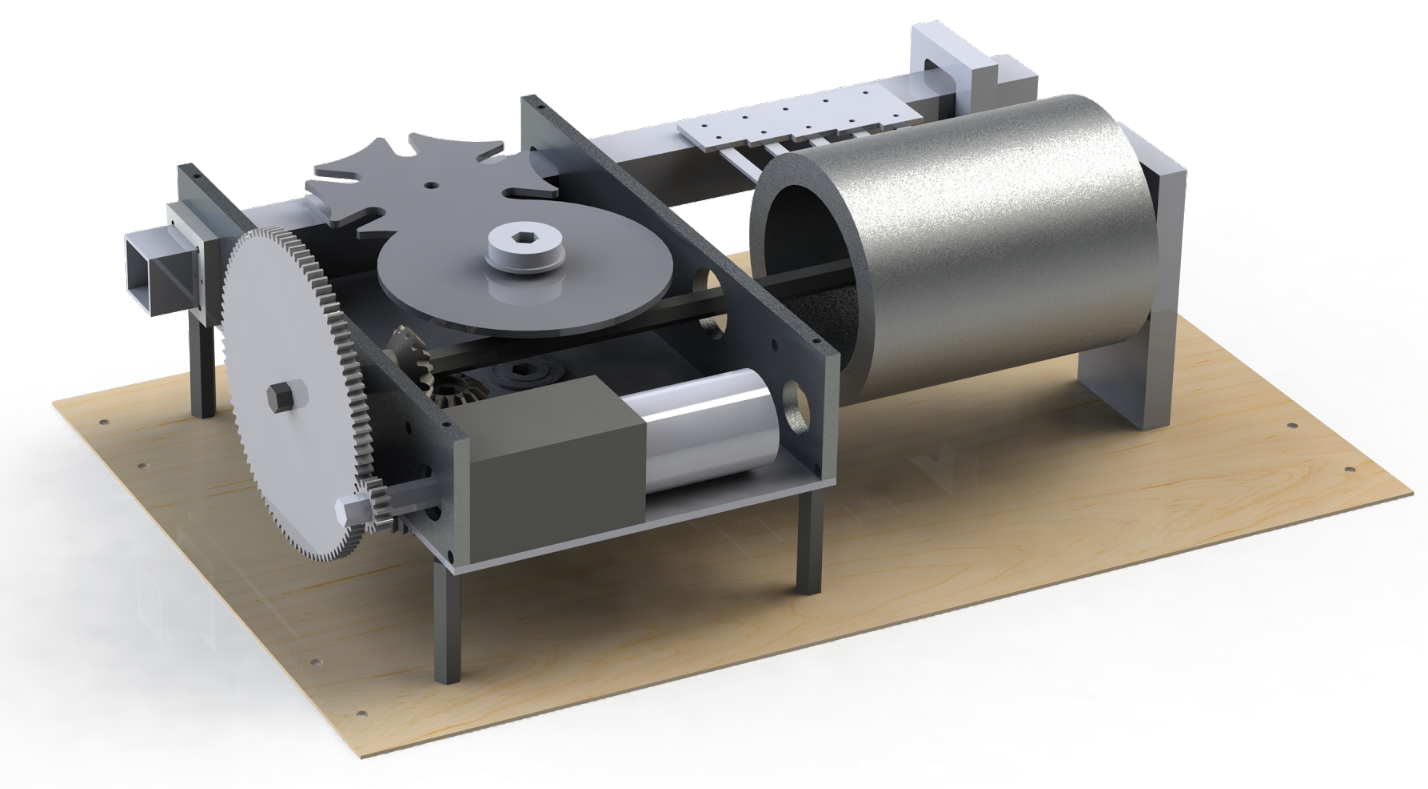
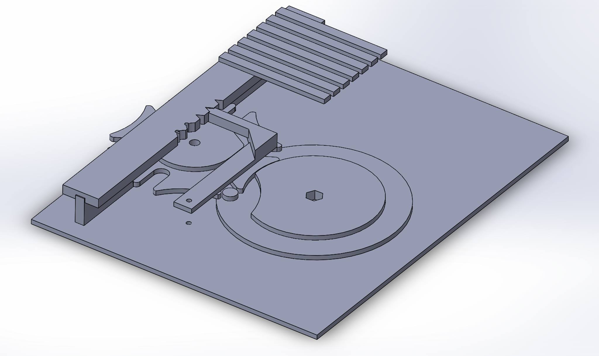
♭Appendix B: Conceptual Drawings
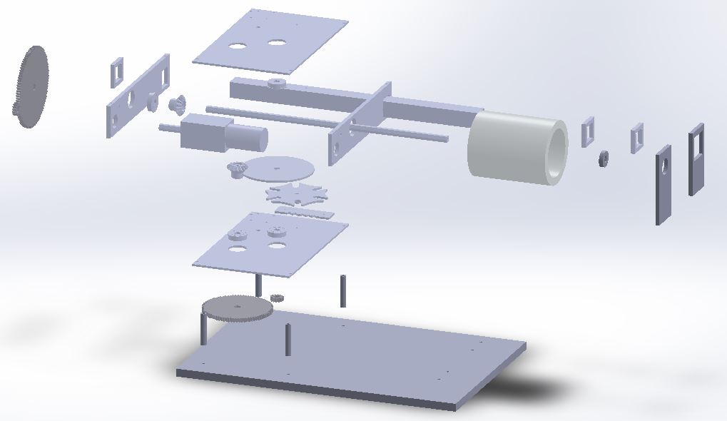
♭Appendix C: 3D Drawings