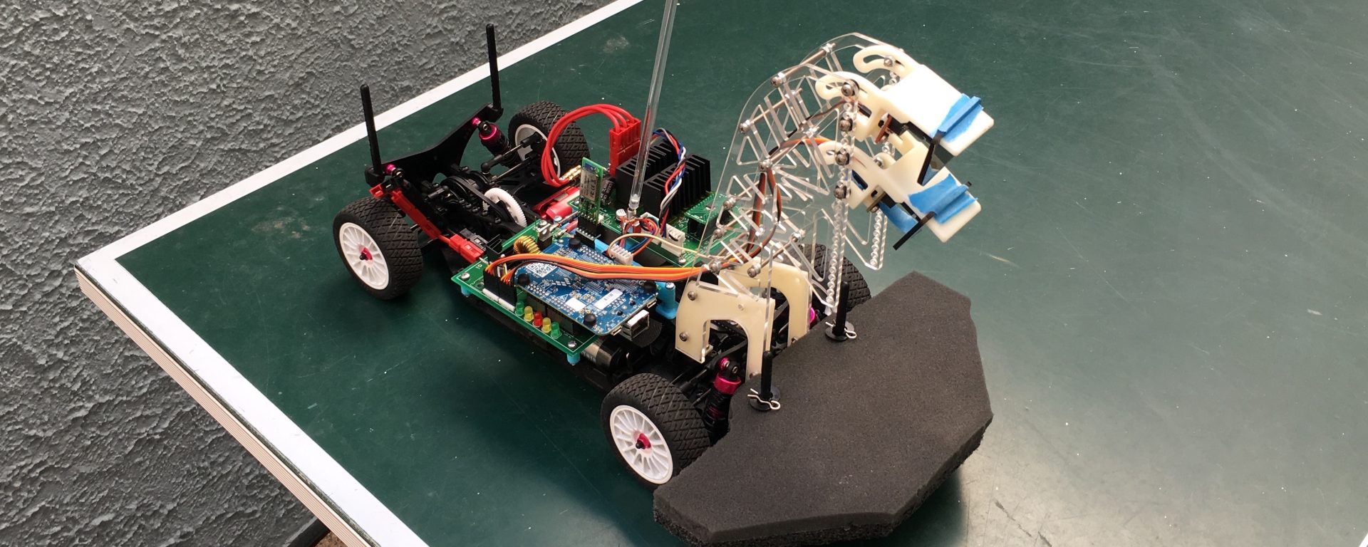
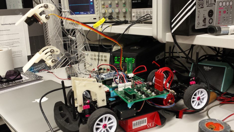
A 1/10 scale, line following race car built to compete in the 2016 UC Davis NATCAR Race. It placed 2nd out of 43 teams. This was made as part of a team project for EE 192 – Mechatronics Design Lab.
See below for project details. Official race results and videos are here. The project presentation with more specifics is here.
Team 1: Fast and Curious — Casey Duckering, Lee-Huang Chen, Cheng Hao Yuan
Chassis
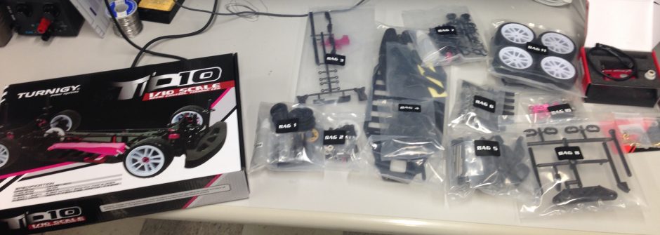
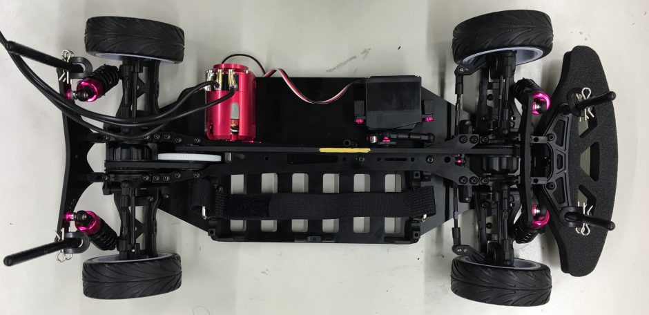
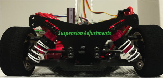
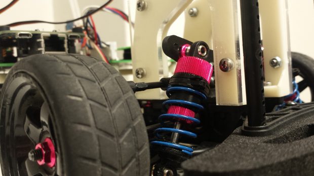
We used an off-the-shelf 1/10 scale racing car kit as the base of the car. Except for this chassis, everything on the car was designed and built by me and my teammates. It is belt driven with front and rear differential, has an analog steering servo, and has adjustable, oil filled shocks. While tuning the car, we frequently swapped out the wheels and the suspension springs to maximize turning speed. The final configuration used rubber wheels in the front and foam in the back.
Motor
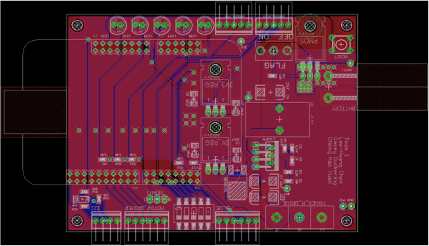
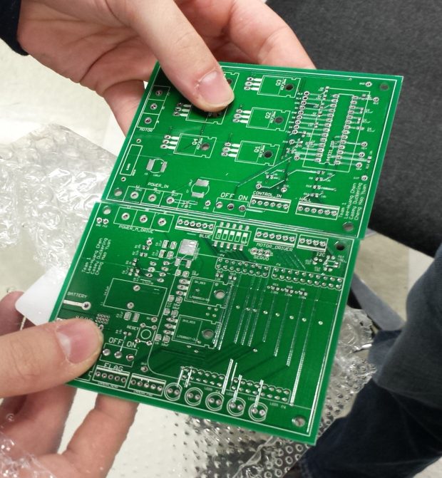
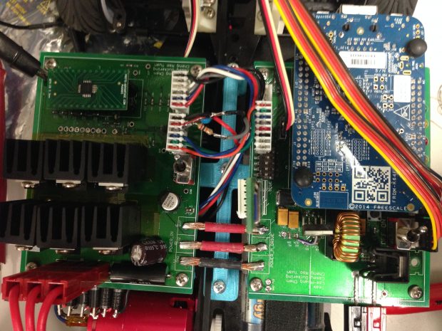
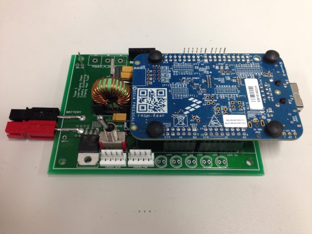
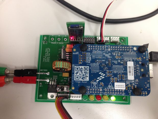
A brushless DC motor with encoder drove all four wheels through a 1.9:1 belt drive. We designed a motor driver using a pre-driver chip and three NMOS half bridges. The pre-driver read the encoder and handled the commutations of the motor so the microcontroller could control it by speed, direction, and braking. The PCB was designed to withstand up to 20 amps of current to the motor (worst case stall current).
Line Scan Cameras
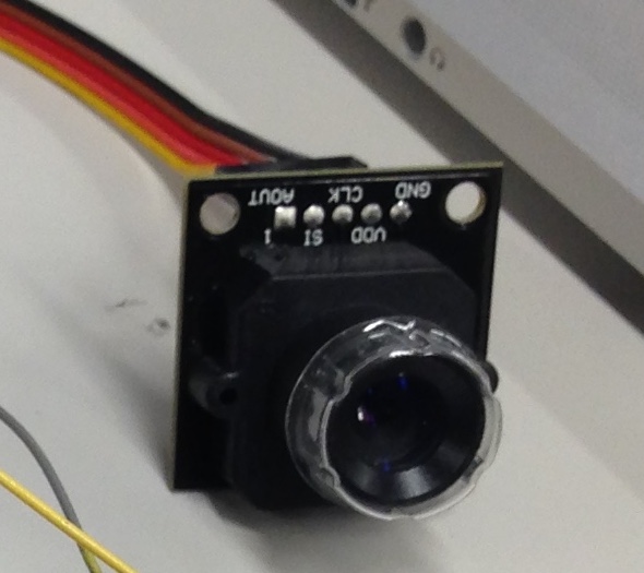
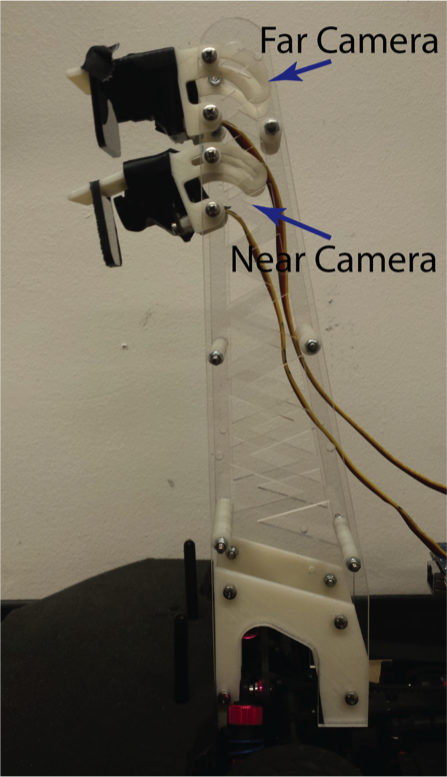
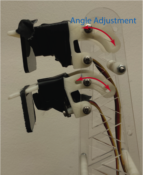
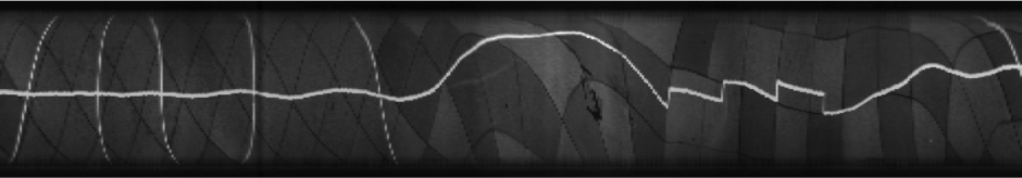
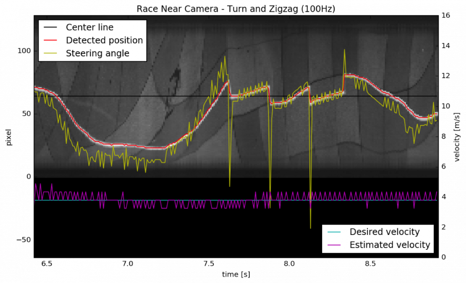
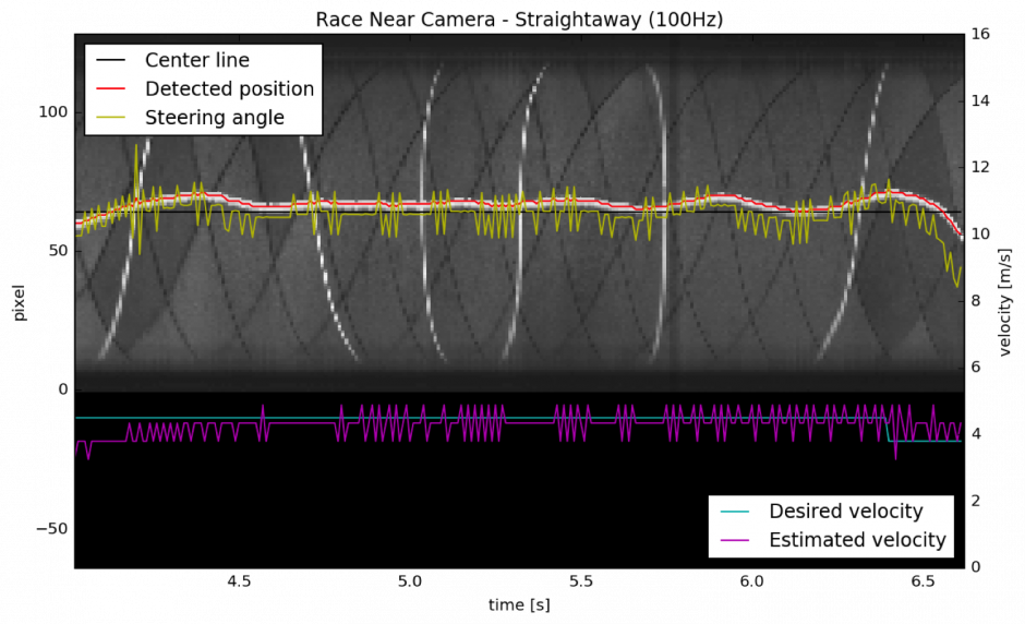
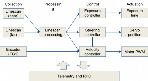
Two 128 pixel line scan cameras are the only sensors used to detect and follow the white line. The pixels are read into the microcontroller through a three wire analog interface. The lower camera is pointed nearer in front of the car and is used primarily for steering. The upper, far camera is used for velocity control and, at high speeds on the straightaways, also used for steering. The pictures above show how the two cameras are mounted to the car and what the near camera sees as the car drives along the line. The microcontroller manually controls exposure and polls both cameras at the 100Hz control rate. A P control loop is used to adjust the exposure to maximize the visibility of the white line as light conditions change.
Microcontroller
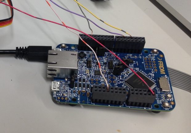
I chose to use the FRDM-K64F development board for this project. It has a 120 MHz clock, 1 MB of flash memory, 256 KB of RAM, an FPU, and supports mbed. This relatively fast clock speed gives plenty of time to process the line scan camera data at the 100Hz control rate.
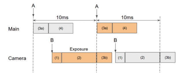
Software control loop timing:
- At interrupt B, camera exposure is started.
- At interrupt A, the camera is read and all of the control calculations and outputs are done.
- The timing of B is set such that B occurs the desired exposure time before A
Telemetry, RPC, and Flashing Over the Air, Remote Control
To speed up debugging and tuning the car, I implemented a few extra features over a wireless serial link. At first, we used a bluetooth serial module but later I upgraded it to a faster WiFi serial interface (using the ESP8266). Telemetry allowed us to see exactly what the line scan cameras were seeing, where the car thought the line was, and what the expected actuator outputs were in real time as the car ran around the track. This allowed us to quickly find any problems and determine what to change to fix them. I based the telemetry code off of work done by a team the previous year.
RPC (remote procedure call) allowed us to set and read variables in the car wirelessly while it was driving. I used the mbed RPC library for this. We mostly used RPC for tuning the motor speed control PI constants, steering control PD constants, and exposure control P constant while it drove around the test track.
Flashing over the air allowed us to more quickly deploy and test new code. At first, to update the code on the car, we had to connect it to a computer with a USB cable then copy the firmware to the microcontroller. This was a hassle and took over a minute so I implemented a function to receive the firmware over the wireless link, write it to flash and restart the processor. This sped up flashing to a couple seconds and it could be done without even taking the car off the test track.
Clicking buttons to control the car is much easier than typing so I wrote a simple web interface to send commands over the wireless serial link instead of typing them in the terminal:
Many Hours of Testing
Determining minimum turn radius at speed:
Test Laps on the outdoor test track in Cory Hall:
Broken Parts
The pre-driver chips were very fragile and we broke many of them over the semester. We suspect the failures were caused by voltage spikes from the motor but snubber capacitors and bypass diodes did not help.
Once, the car drove under a chair at high speed and smashed the camera mount. We glued it temporarily then laser cut a new one.
Right before one of the class races, the hub broke out of a front wheel. We had to replace it and quickly verify that car’s traction had not changed too much.
Cheng, soldered the bypass diodes wrong causing all six power NMOS to turn on, shorting the battery. Luckily the PCB withstood the current and we only had to replace a few components.
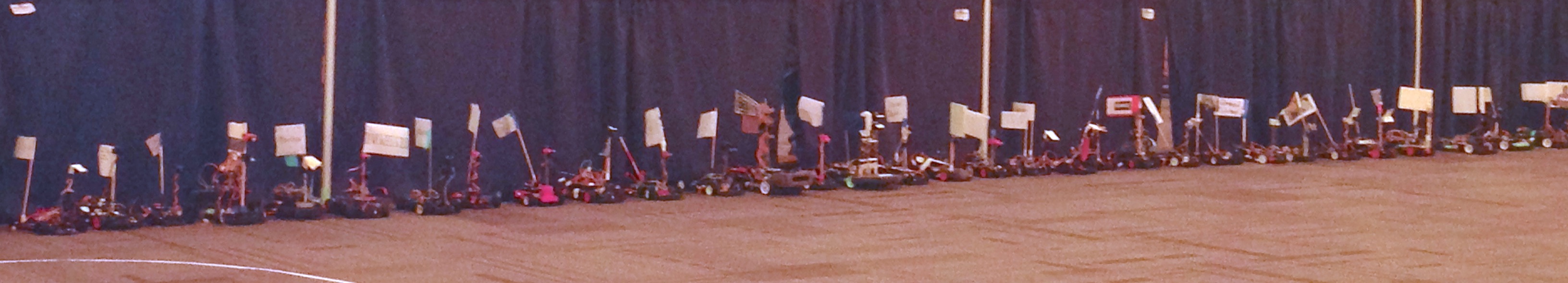
NATCAR at UC Davis
At UC Davis, we spent the entire practice time tuning the suspension and testing different wheels for optimal traction on the carpet and determining the maximum speed. None of the control algorithms needed to be retuned for the new environment.
During the race, each team gets five minutes total on the track to do as many laps as they want. Only the fastest lap is counted. Here are some of our laps (our best is at the top of the page):