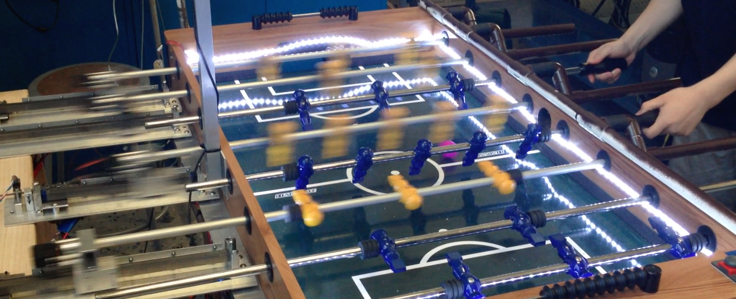
A Foosball table that plays against you. It sees the ball with an overhead camera and moves the opposing men with actuators mounted to the side.
See below for project details.
https://youtu.be/1kIAKEqdcnM&w=840&rel=0
https://youtu.be/qfRf8OJM0xg&w=840&rel=0
https://youtu.be/BTtUcNgVP2U&w=840&rel=0
https://youtu.be/II1cp98ob4c&w=840&rel=0
Background and Motivation
Siblings are oftentimes great playmates and who usually make our childhood happier, but that is not a luxury an only child can have. More than half of our group members are only children, and we have all experienced the days we talked to ourselves, played chess/card games with ourselves, and wished we have someone to play with.
To address this issue for the only children, we decided to build a robotic foosball player to be their playmate. One might ask why we don’t just code up a new video game on PC, PS3, or smart phones, and our answer is, physical fun is healthier and makes people happier. Currently, there are way too many people playing candy crush and various smart phone games constantly. This makes their eyesight suffer and they only get sleepier afterwards. We do not want to see that happen to the young children who just want a playmate. Therefore, our project would feature physical fun that reminds people the world outside of their smart phone screens is much more beautiful and fun. A game of foosball makes you energetic and maybe even sweat a bit, and that feeling is priceless – trust us, we have carefully tested this.
The motivation is important, but the class requirement for the project is just as, if not more, essential. The robotic foosball player integrates all the requirements cohesively. Following is a summarized list of how these requirements are met and we will elaborate more in later sections:
Real-Time and Multitasking
- Position control for man location and kicking
- Computer vision to determine current ball location
- Kalman filter to predict ball location
Interaction with the External World
- Vision system
- Actuators controlling men
Component Running on Multiple CPUs or Cores
- Two myRIOs
- One Arduino
- Four motor controllers
- One Computer
GUI
- Scoring board with buttons to activate or stop the game
Predicted Challenges
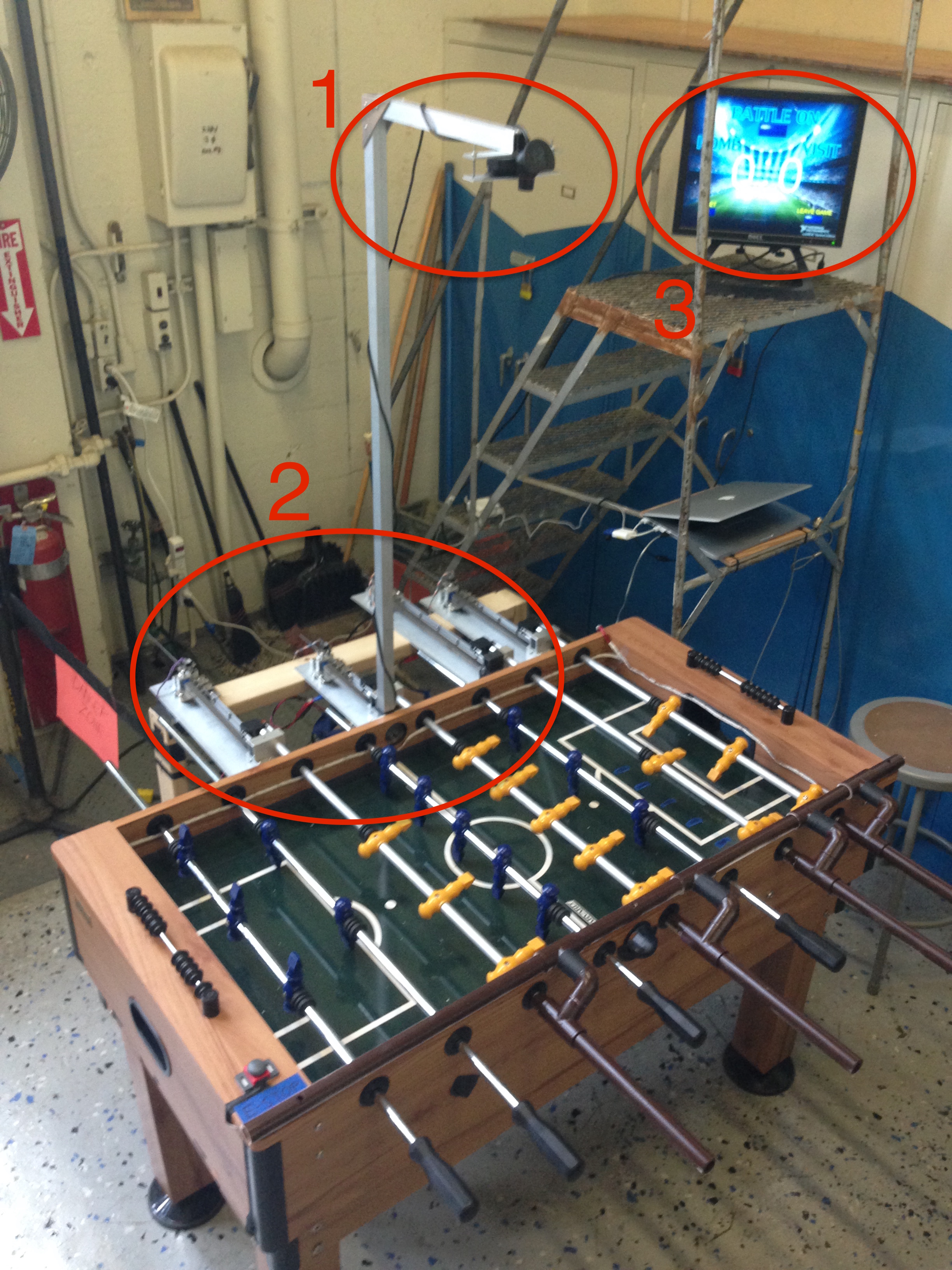
This project was predicted to consist of three main parts: vision (1), actuation (2), and GUI (3). The vision system would consist of an overhead camera to view the position of the ball connected to a myRIO to do the computer vision to find the location of the ball and to do kalman filter calculations to find its velocity. The camera frame rate was desired to be 100 fps to track high speed kicks.
The actuation system would consist of logic and output to motor controllers. The logic would decide on the position and angle for all the men on the field to defend the goal and to score. The myRIO would then output these desired positions and angles to off-the- shelf motor controllers and servos to drive our mechanical system.
The GUI would show the current game score and allow the user to enable or disable the actuators.
Mechanical Challenges
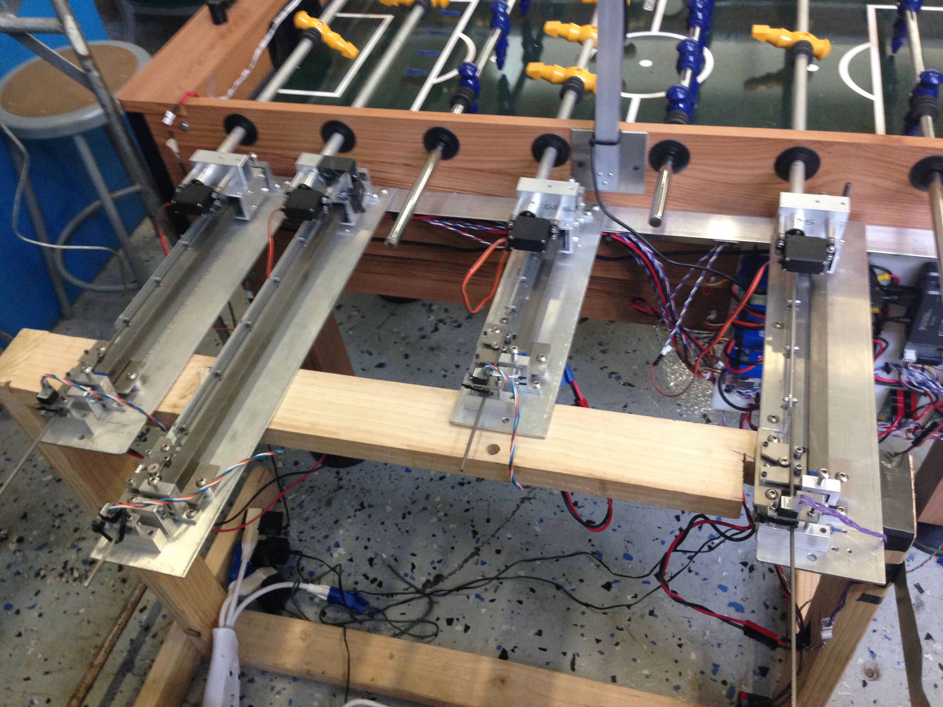
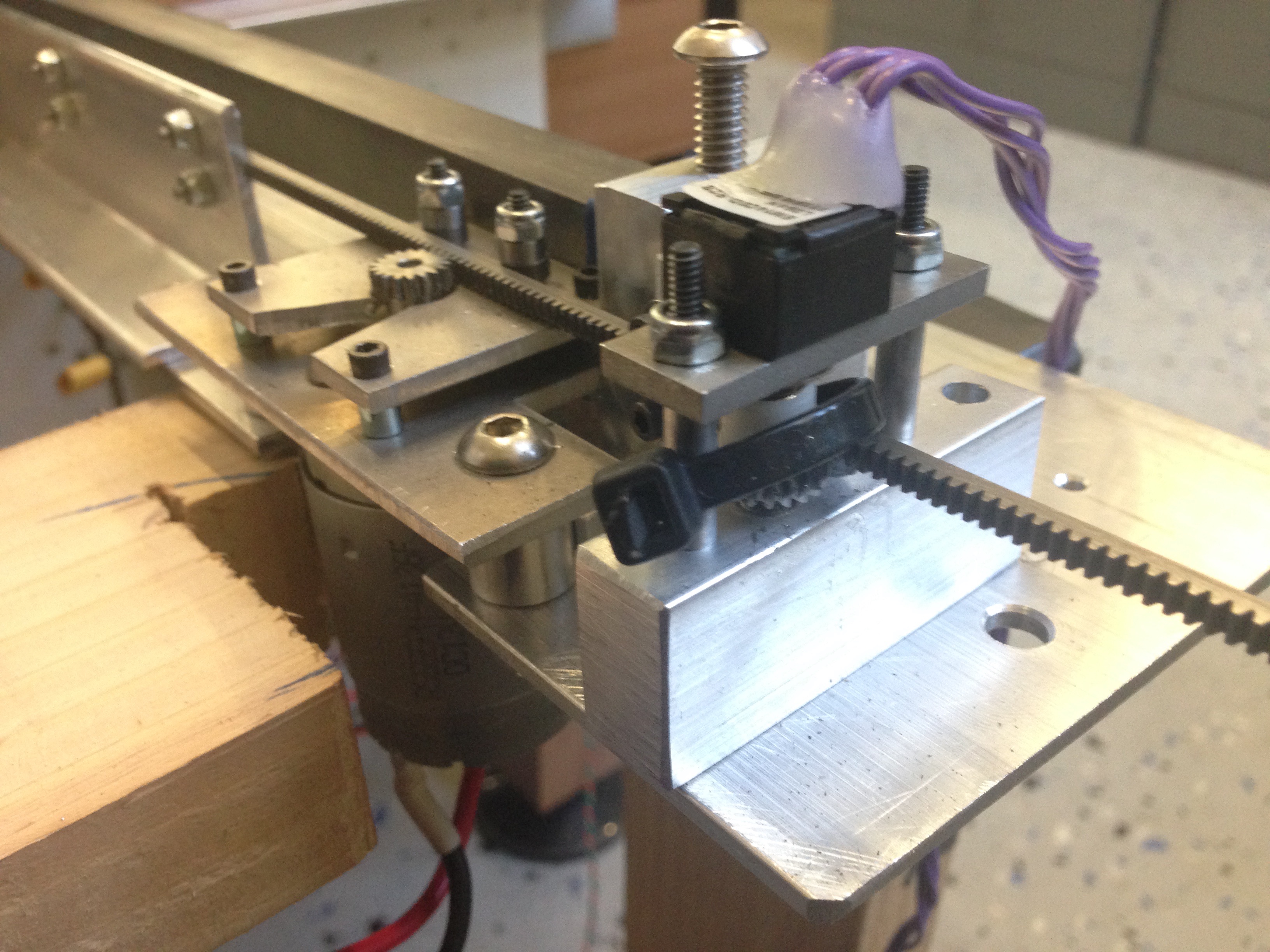
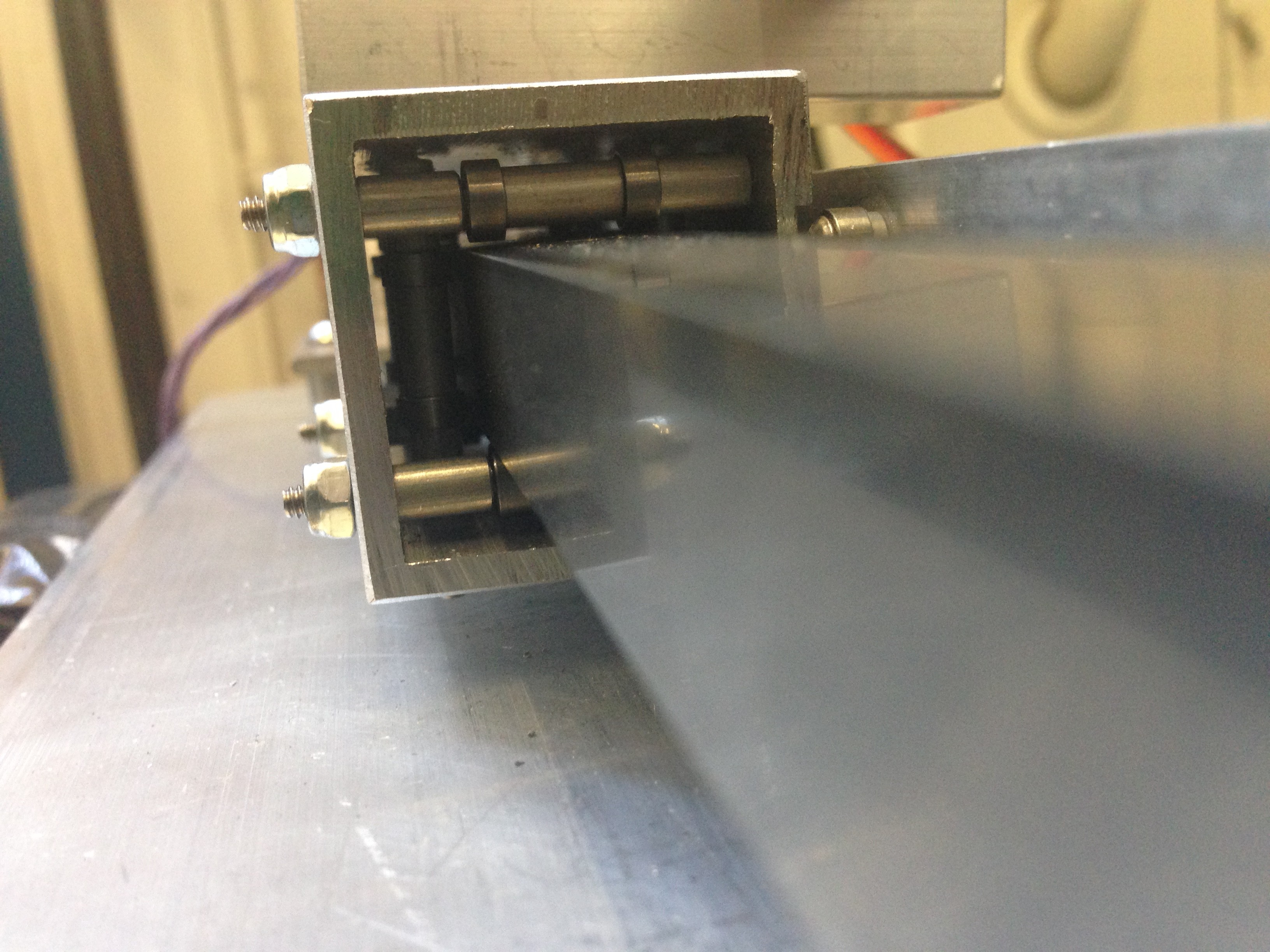
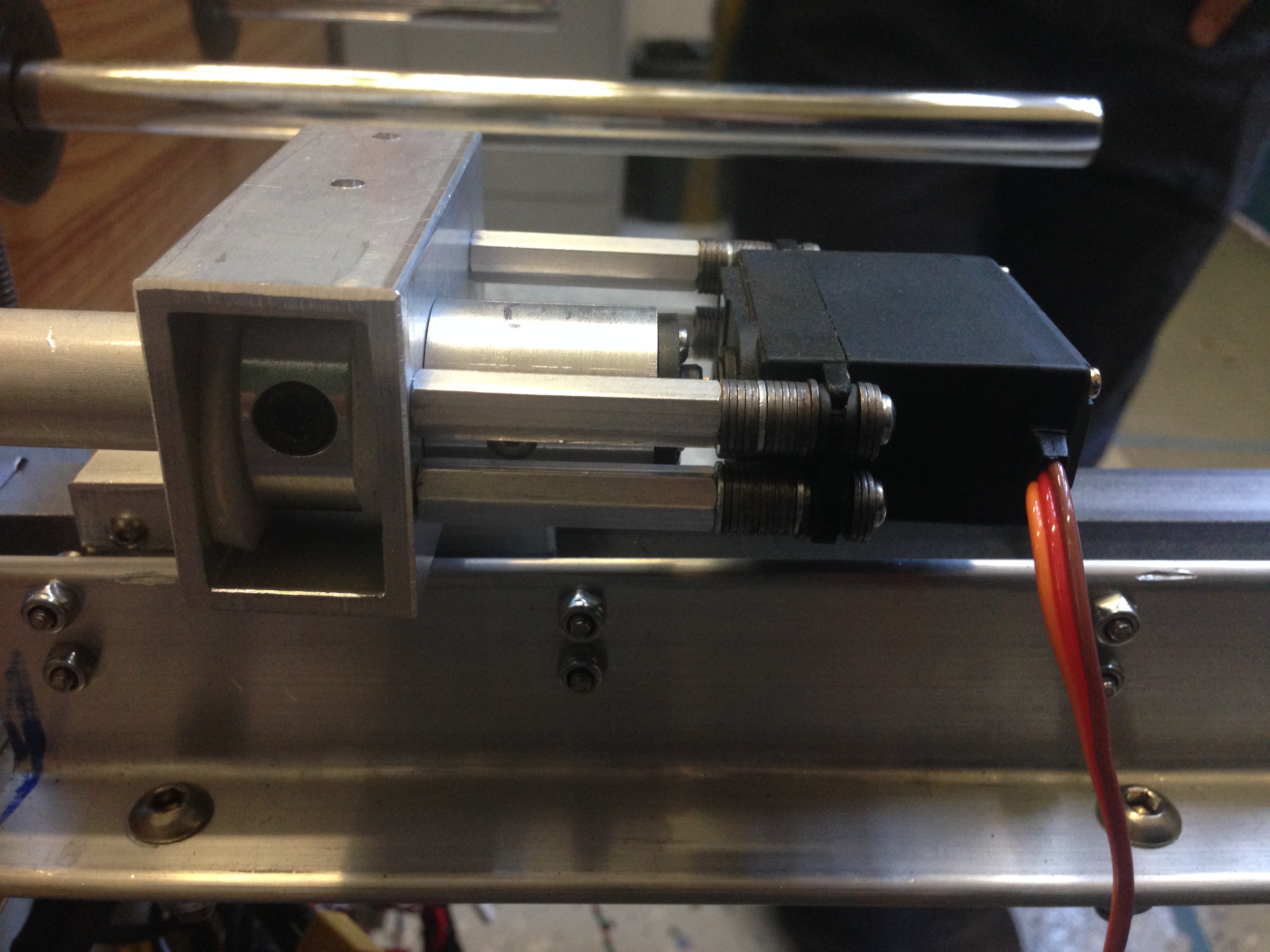
In order to determine our system specifications, we examined the dynamics of a foosball game. We took videos of a foosball game, and determined the maximum ball velocity that occurred commonly in the game. From the video footage, we determined that there would be challenging lateral response characteristics to meet: the rods must laterally move at almost 1.5 meters per second, in the worst case scenario. Essentially, the rods must controllably move 7 inches, in .1 seconds, in the worst case. Because normal class systems would not meet those performance specifications, we determined that we must construct custom linear actuators to meet those specifications.
Secondarily, our system must be capable of rotary rotation of the foosball rods, in order to kick the ball back towards the opponent. Using the video footage, we identified that a high-speed rotary actuator would ideally be useful. However, position control of the rods is important, to allow all rods to block, or get out of the way of the ball, as appropriate.
Software Challenges
Our main predicted software challenge was to process each camera frame in under 10ms to achieve the desired 100 Hz update rate. We planned to use the onboard FPGA on the myRIO to accomplish this. Other challenges included writing an AI smart enough to move and kick with proper timing to block and score, tuning the Kalman filter to respond to fast changes in velocity but also have sufficiently low noise, and making sure all of these calculations ran in under 5ms.
Actual Challenges
Actual System Overview
The final system we build was very similar to our planned system with a few additions and changes to solve challenges we found while building it. We encountered significant challenges implementing computer vision on the FPGA and instead implemented it on the CPU of the myRIO. To reduce the processing load on the myRIO, we moved the computer vision code onto a second myRIO. This myRIO took frames from the camera and sent ball locations to the first myRIO over UART and we were only able to achieve 25 Hz instead of the planned 100 Hz update rate. We also added LED lighting around the field to improve reliability under various light conditions.
The Kalman filter and artificial intelligence logic worked as planned and ran on the first myRIO after receiving the ball locations over UART. We also implemented an extra feature, automated score counting, that used the estimate of the ball velocity to check if the ball went through either goal and incremented the appropriate score counter. These three components took several days to fully tune.
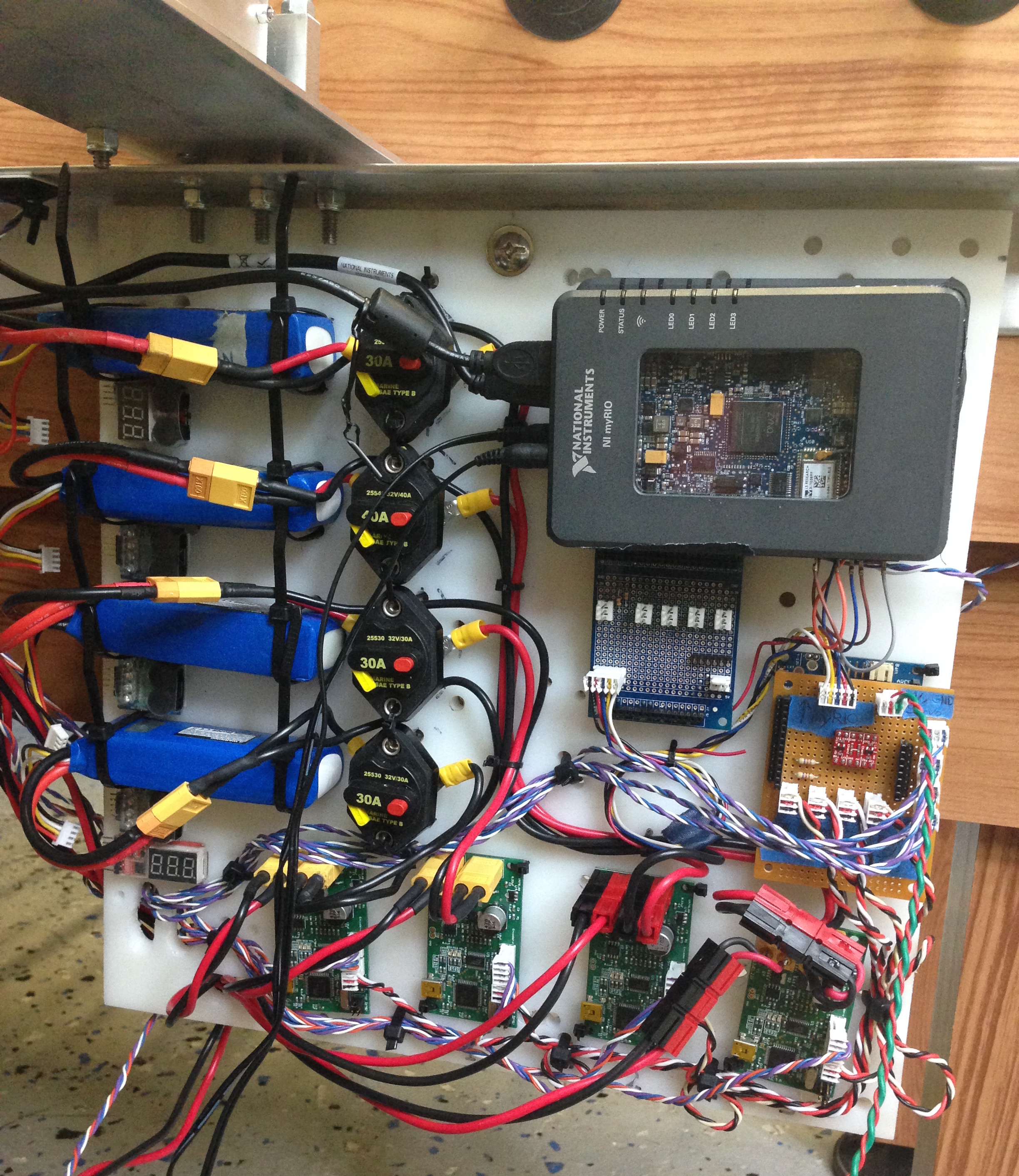
The final software component running on the myRIO outputs the desired linear actuator and servo positions over UART to an Arduino microcontroller configured to forward commanded positions to the four servos over PWM and the four Grizzly motor controllers over I2C.
Finally, the mechanical portion of the project is controlled. The motor controllers drive each of the four motors to move the foosball men and the servos turn the men to kick and block. A rotary encoder, connected to a motor controller, is mounted along the rack of each linear actuator and the linear position is controlled using built-in PID on the motor controllers. We tuned the PID constants for maximum responsiveness with some overshoot.
As an extra safety feature, we added an emergency stop button to the table that disables all of the actuators immediately if someone presses it.
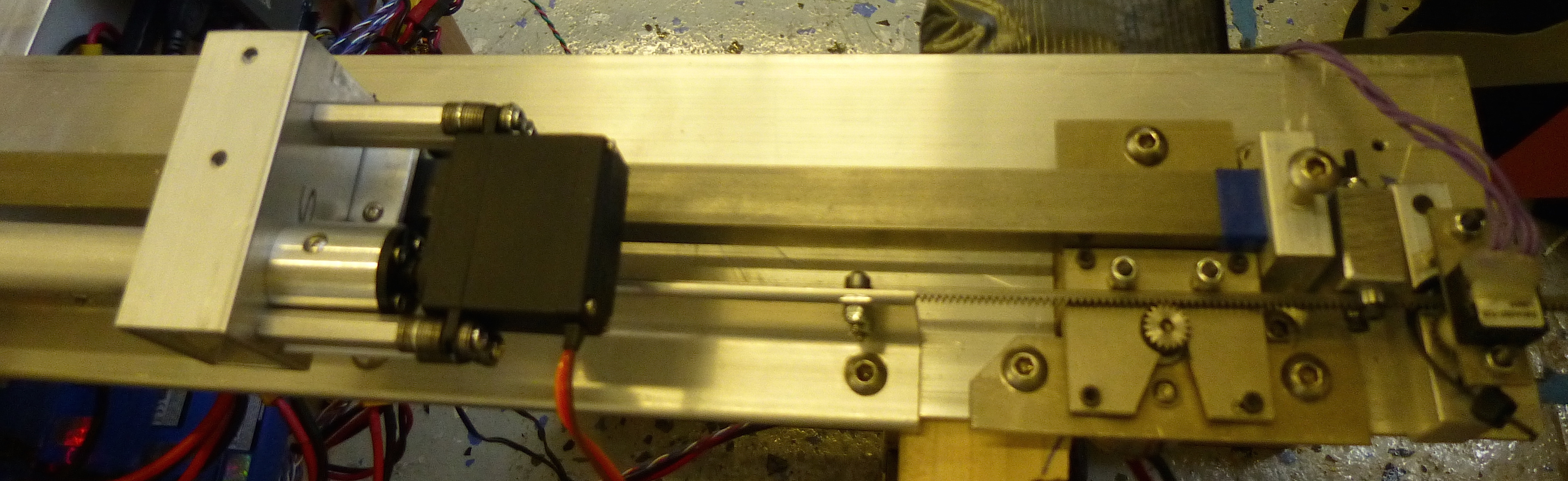
One major challenge to overcome was the design of the linear actuator itself. The tight performance requirements, and the low design cost, necessitated a unique design with tight tolerances. This design required a complete prototype to develop – a challenging requirement, given the the time constraints of the semester.

Software Challenges
We had several software challenges while making this project, one of the main ones with regards to the software side of this project was communication between the myRIO and the motor controllers. The software on the motor controllers was configured to offer both open loop speed and PID position control, so the myRIO merely needed to communicate the configuration settings and update the target speed or position for each actuator. As the motor controller’s primary form of communication is through the I2C protocol, it was attempted to use the myRIO I2C directly. After much testing it was determined that the myRIO’s internal timing was unreliable when communicating between chips from different manufacturers. A solution was found in communicating via UART to an Arduino microcontroller, which would then relay over I2C the configuration to each motor controller.
One challenge we did not expect at all was the myRIO did not support the camera we choose, the PS3 EyeToy. After scouring the internet for camera drivers that worked on NI’s custom Linux OS that runs on the myRIO and finding nothing, we decided to take open source driver code for the EyeToy and compile manually it for myRIO. The driver worked and the camera was recognized by LabVIEW.
Another major challenge was implementing computer vision on the FPGA. We first implemented a calculation of the centroid of the camera frame after applying a threshold. This mostly worked and processed the image in under 5ms, sufficient for the 10ms we required. However, the centroid algorithm was extremely sensitive to a small amount of noise or lighting change in the image and often gave noisy data several inches away from the correct location due to false positive pixels. Replacing the centroid algorithm with a blob detection algorithm gave us 100% accuracy under various lighting conditions when we tested a CPU implementation. The downside was it took 40 ms to process a frame on the myRIO CPU and writing blob detection for the FPGA would have both been extremely challenging and the onboard FPGA would not have been large enough to run it. We decided to use the slower but reliable software implementation of blob detection.
In regards to controlling the actuator, we ran into an issue of the linear slider overshooting and crashing into the table, which is clearly undesirable. Therefore, knowing that a large “step” command would cause large overshooting because amount overshoot is related to damping factor and value of the “step” command, we generate a series of smaller steps in software to guide the actuator to reach the desired position at a velocity it can actually move at. Since each step is of a smaller value, the amount of overshoot is significantly reduced because there is no integral build up but we are still able to maintain a similar response time.
Future Revisions
Design Changes
The primary change we would make in the mechanical design is in the rotary actuation. The servo motors that we used were far too weak, and the men kind of just sadly pushed the ball rather than producing a solid kick. We plan to change this to a regular motor in the future to increase the speed of the kicking. However, this option does have its potential drawbacks. It will add more weight to the servo assembly, so we will need to redesign the linear actuator as well. We will need a stronger motor to move the added weight, and possibly use a belt or chain as opposed to a rack and pinion. A chain would be much less fragile than the rack and can withstand the increased forces, but would not work as well with the large travel distances required by the rods due to it sagging under its own weight. Overall, we are presented with a new set of design challenges. By solving them, we can ultimately create a stronger kicking mechanism while keeping the performance of the slider comparable to, if not better than, the initial design.
Changes we would make to the vision system in the future would include improving the speed to our originally desired 100 fps and increasing the position precision. We would do this either by using a more powerful computer with a GPU to process the camera image, getting a larger FPGA and implementing blob tracking on it, or using an off the shelf vision tracking system (although none in a reasonable price range can capture 100 fps yet). We would probably go with the first option.
Different Features
In developing the robotics foosball player, there are a few different features that were considered that would have been interesting to implement had there been more time. One of the improvements that could be made would be in the strategy for blocking and kicking. As of now the movement strategy for the men is a rather simple strategy of blocking whenever the ball is in front, kicking when he ball is in front of a man and stationary, and lifting out of the way when a row behind is kicking. With the addition of a better kicking mechanism we could implement a more coordinated and aggressive offensive strategy, including dribbling the ball between men on the same row, passing the ball between rows, and aiming kicks at angles for scoring goals (possibly even bouncing the ball off the walls for these strategies).
An extension of this idea would be to actually implement different AI personalities or levels of difficulty. One AI could be purely defensive, one could have an organized attacking strategy, and one could constantly spin the men at max kicking power. The AI could even be programmed to make fun of the human opponent whenever they get scored on for the ultimate robotics foosball experience.
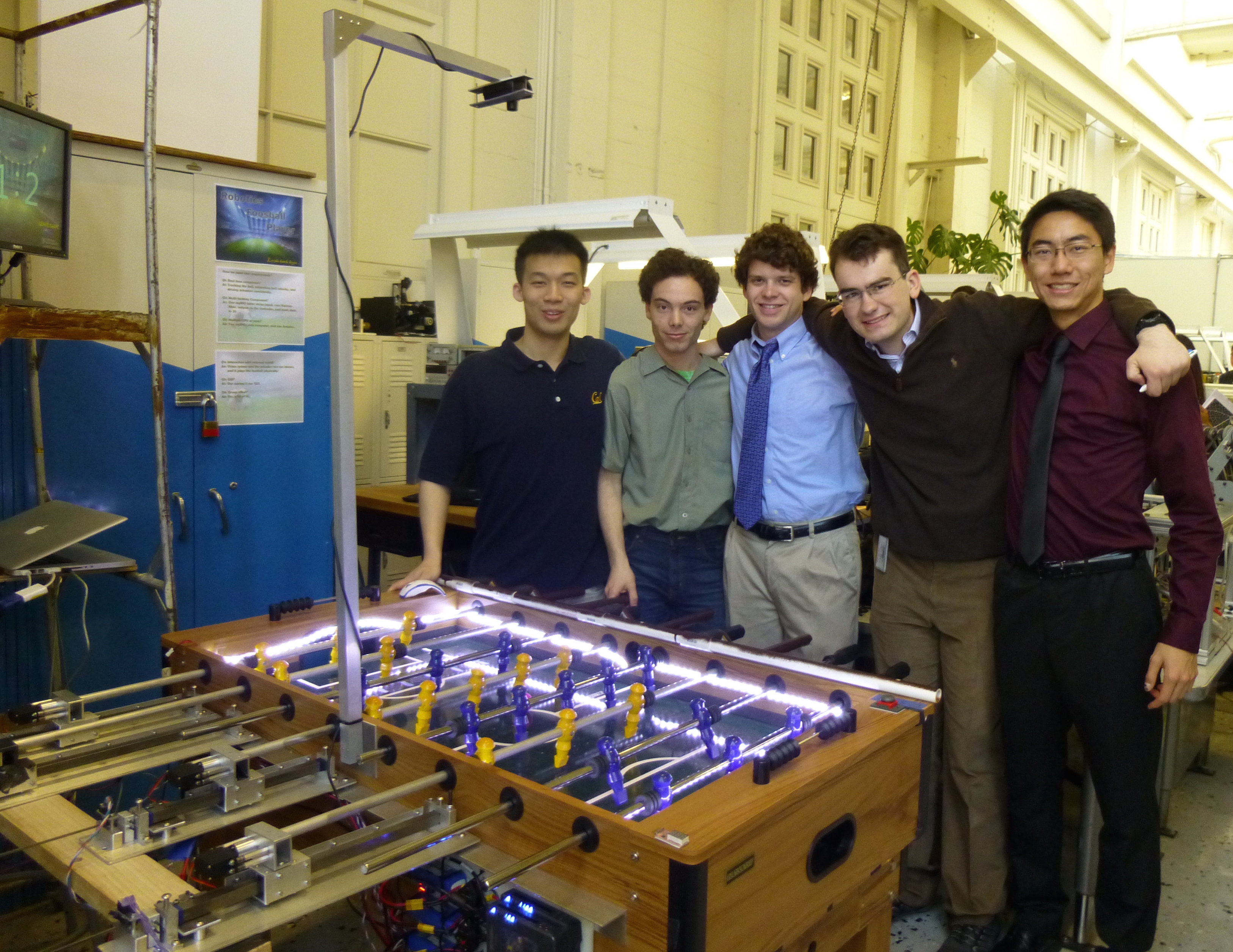
Acknowledgements
We would like to thank Dr. George Anwar, Matt Cameron, and Sunita Venkatesh, and Pioneers in Engineering for all their support. This project would not have been possible without your help.